
Related Manuals for Megaimpulse RC20


Summary of Contents for Megaimpulse RC20
- Page 1 RC20 RESISTIVE COUPLER FOR NPG SERIES NANOSECOND PULSE GENERATORS USER MANUAL © 2023 Megaimpulse Ltd. V2.0 of February 07, 2023...
- Page 2 LOSS OF PROFITS, LOSS OF BUSINESS, LOSS OF USE OR DATA, INTERRUPTION OF BUSINESS AND THE LIKE), EVEN IF MEGAIMPULSE LTD. HAS BEEN ADVISED OF THE POSSIBILITY OF SUCH DAMAGES ARISING FROM ANY DEFECT OR ERROR IN THIS MANUAL OR PRODUCT.
-
Page 3: Table Of Contents
Application, general view, and package content ..........2 Safety manual ....................3 Technical specification ..................4 The drawing of RC20 resistive coupler ............5 Assembling and putting into operation ............. 6 Theory of the operation ..................8 Energy loss in a cable. Calculation of the energy balance ........ 14 Evaluation of the pulse voltage on the load and the pulse current .... -
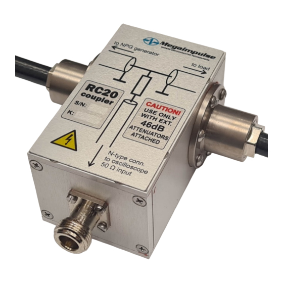
Page 4: Application, General View, And Package Content
5 meters in length each. PACKAGE CONTENT Please check the package for the following items: RC20 resistive coupler with two attached HV coaxial cables of 5 meters in length each; 6 dB attenuator with N-type connectors; 20 dB attenuator with N-type connectors;... -
Page 5: Safety Manual
SAFETY MANUAL Electrical safety RC20 resistive coupler is designed for the precise measurement of nanosecond high-voltage pulses. Please be very careful while working with high-voltage equipment, and operate by qualified personnel only. Improper use may result in electric shock, strong electromagnetic ... -
Page 6: Technical Specification
Rise time (transient response) 1.5 ns Nominal pulse voltage attenuation of RC20 coupler 1:50 (34 dB) * RC20 with 46 dB attenuators 1:10000 (80 dB) Impedance and length of HV cables 75 Ohm, 5 m + 5 m Output connector to the oscilloscope N-type, 50 Ohm impedance approx. -
Page 7: The Drawing Of Rc20 Resistive Coupler
* All the dimensions are in mm and are given for the reference only Fig. 2. The drawing of RC20 resistive coupler. 1 - HV coaxial cable to the NPG generator. The length is 5 meters; cable impedance is 75 Ohm. Standard 75 Ohm coaxial connector is installed on the generator's side. -
Page 8: Assembling And Putting Into Operation
Step 1. Unpack the package and check the presence of the following items: RC20 resistive coupler with two attached 5 m HV coaxial cables; 6 dB attenuator with N-type connectors; 20 dB attenuator with N-type connectors; 3 m semirigid coaxial cable assembly with N-type and SMA connectors;... - Page 9 Fig.4. RC20 resistive coupler assembling and connection. Step 3. Connect the HV cables to the NPG-series pulse generator and to the load as well as connect RC20 to the oscilloscope. Set the input impedance of the oscilloscope to 50 Ohm.
-
Page 10: Theory Of The Operation
Ohm after it. Part of the pulse energy inevitably reflects from the load and travels back to the generator. RC20 coupler is a measurement tool of the incident and reflected pulse waveforms, which allows us to calculate the energy of both pulses, and therefore, determine the energy balance or energy efficiency of the discharge. - Page 11 = 75 Ohm is the cable impedance. CABLE The absorbed by the load energy E can be easily calculated from the energies LOAD of the incident E and reflected E pulses: ���� = ���� − ���� − ���� ���������������� ���� ���� ���������������� RC20 User Manual...
- Page 12 . This question will be discussed in the next chapter in precise calculation of E LOAD more detail. RC20 operation in case of low and high impedance loads are schematically shown in Fig.7 and Fig.8. Fig. 7. The incident (red) and reflected (blue) pulses for short or low-impedance load.
- Page 13 The propagation directions of the incident and reflected pulses are pointed by the arrows. RC20 User Manual...
- Page 14 As an example, the oscillograms of the incident and reflected waveforms for the first and the second pulses in a burst registered by RC20 coupler in case of 1 mm gap discharge at ambient pressure are shown in Fig.10 and Fig.11. The pulse-to- pulse interval within a burst is 10 µs (100 kHz repetition rate).
- Page 15 Fig. 11. The incident and reflected waveforms of the second pulse in a burst for 1 mm gap discharge. The discharge occurs at much lower voltage. The scales are 5 kV/div and 10 ns/div. RC20 User Manual RC20 User Manual...
-
Page 16: Energy Loss In A Cable Calculation Of The Energy Balance
1.0123 times while the pulse travels along one meter of HV cable. The cable length between RC20 coupler and the load is 5 meters. Therefore, the energy loss on 5 meters of travel is 0.265 dB, or the attenuation coefficient is k = 1:1.063. - Page 17 And again, it is attenuated by 1.063 times while the pulse travels from the load to RC20 coupler. Therefore, we should multiply the registered energy of the reflected pulse by 1.063 to get the real reflected pulse energy 16.163*1.063≈17.18 mJ.
-
Page 18: Evaluation Of The Pulse Voltage On The Load And The Pulse Current
EVALUATION OF THE PULSE VOLTAGE ON THE LOAD AND THE PULSE CURRENT RC20 can help to evaluate the pulse voltage on the load and the pulse current. At first, the exact delay between the incident and reflected pulses should be measured. - Page 19 Fig.15. The equivalent electrical circuit of the discharge reactor. STRAY can be made as low as 1 pF and below, which results in its minor influence. STRAY Indeed, the current through is equal to: RC20 User Manual...
- Page 20 Fig.14 at t = 6 ns and after. STRAY RC20 allows us to measure precisely, which may be useful for the discharge simulation. In addition, changing the stray parameters can help to adjust the pulse waveform on the load.
- Page 21 The calculated stray inductance in this experiment is 122.7 nH. RC20 coupler registers the pulse waveform reflected from the load which consists of the discharge gap itself, stray capacitance, and stray inductance of the wires/electrodes. The calculated pulse voltage is not exactly the voltage on the gap, one should consider the stray parameters too.
-
Page 22: Warranty
WARRANTY Please see your sales agreement to determine the warranty period and condition. Removing the warranty seals and labels terminates the warranty. MEGAIMPULSE LTD.
Need help?
Do you have a question about the RC20 and is the answer not in the manual?
Questions and answers