Advertisement
Quick Links
Advertisement

Related Manuals for Megaimpulse CS-10/500


Summary of Contents for Megaimpulse CS-10/500
- Page 1 CURRENT MEASUREMENT SHUNT CS-10/500 USER MANUAL © 2017 Megaimpulse Ltd.
- Page 2 FOR LOSS OF PROFITS, LOSS OF BUSINESS, LOSS OF USE OR DATA, INTERRUPTION OF BUSINESS AND THE LIKE), EVEN IF MEGAIMPULSE LTD. HAS BEEN ADVISED OF THE POSSIBILITY OF SUCH DAMAGES ARISING FROM ANY DEFECT OR ERROR IN THIS MANUAL OR PRODUCT.
-
Page 3: Table Of Contents
CONTENTS Package content ....................2 General view of CS-10/500 current measurement shunt ........2 Safety manual ....................3 Technical specification ..................4 The drawing of CS-10/500 current measurement shunt ........5 Putting the shunt into operation ................ 6 Warranty ......................10... -
Page 4: Package Content
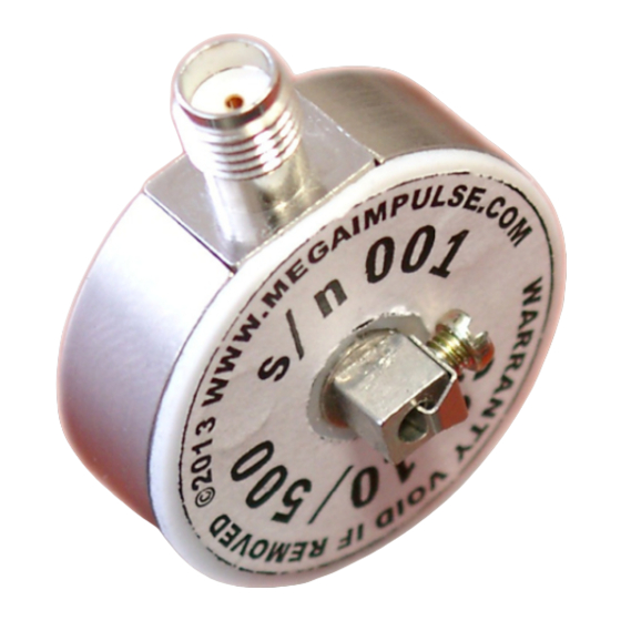
Please check the package for the following items: CS-10/500 current measurement shunt (hereinafter "shunt") 20dB 18 GHz attenuator with SMA connectors coaxial cable assembly with SMA connectors SMA-to-BNC adapter Fig. 1. General view of CS-10/500 current measurement shunt. MEGAIMPULSE LTD. -
Page 5: Safety Manual
SAFETY MANUAL Electrical safety CS-10/500 shunt is designed for short pulse current measurement in high voltage circuits. Please be very careful and operate by qualified personnel only. There is a risk of electric shock, strong electromagnetic interference, damage of electronic equipment in case of improper use. -
Page 6: Technical Specification
TECHNICAL SPECIFICATION OF CS-10/500 CURRENT MEASUREMENT SHUNT Current/voltage transfer ratio: without 20dB attenuator 10 A/V with 20dB attenuator 100 A/V Peak pulse current 500 A Pulse polarity Rise time (transient response) 1 ns Internal impedance 0.2 Ohm (in measured power circuit) -
Page 7: The Drawing Of Cs-10/500 Current Measurement Shunt
(top on the figure) should be connected to the load, ground shunt contact (bottom in the figure) should be connected to HV coaxial cable ground contact. Fig. 2. The drawing of CS-10/500 current measurement shunt. CS-10/500 shunt user manual... -
Page 8: Putting The Shunt Into Operation
The shunt should be installed in the break of the load ground wire, i.e. between HV coaxial cable ground wire (cable braid) and load ground contact (please see Fig.3). Fig. 3. Set up of CS-10/500 current measurement shunt serially with the load. MEGAIMPULSE LTD. - Page 9 Step 4. Set the following oscilloscope operation regime (see Fig. 5): Input impedance of the oscilloscope channel – 50 Ohm; External attenuation – 100:1 (100x); Couping – DC; Bandwidth – full; Scale 50 V/div or 100 V/div. CS-10/500 shunt user manual...
- Page 10 Fig. 6. The simultaneous pulse voltage and current measurement by Tektronix P6015A probe and CS-10/500 shunt is shown in Fig. 7. Please connect the oscilloscope ground clip contact just to the ground contact of the shunt. It should be noted that simultaneous voltage-current measurement may lead to higher interference and noisy registered signal.
- Page 11 One can see output HV coaxial cable fixed by the clip, simple barrier discharge load made of two copper foils separated by polyimide film and CS-10/500 shunt. Fig. 7. Connection of P6015A probe and CS-10/500 shunt for simultaneous pulse voltage and pulse current measurement. CS-10/500 shunt user manual...
-
Page 12: Warranty
WARRANTY Please see your sales agreement to determine the warranty period and warranty condition. Warranty terminates if the shunt label is removed as well as in case of mechanical damage of the shunt or improper operation. MEGAIMPULSE LTD.
Need help?
Do you have a question about the CS-10/500 and is the answer not in the manual?
Questions and answers