
Related Manuals for MB QUART MB QUART Stage 3 MBQR-STG3-2


Summary of Contents for MB QUART MB QUART Stage 3 MBQR-STG3-2
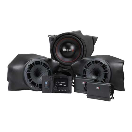
- Page 1 Installation Manual MBQR-STG3-2 MBQR-STG3-RC1 STAGE 3 800 WATT / THREE SPEAKER RZR-Tuned Audio Package for Polaris Vehicles ® ®...
- Page 2 Thanks for choosing MB QUART! The RZR-Tuned Stage 3 Audio System Kit has been meticulously engineered for your vehicle. The process of installation is simple and straightforward. Installation following these detailed instructions can be completed in about 3.5 hours. INSTALLATION OVERVIEW VIDEO products feature a “how to”...
- Page 3 INSTALLATION TIME About 3.5 hours are required to complete this installation. TOOLS AND SUPPLIES NEEDED share the pictures of your installation on MB Quart social media channels to help others. SAFETY PRECAUTIONS Safely prepare your machine for the installation before proceeding.
- Page 4 TWO RZR-TUNED STAGE 3 AUDIO SYSTEM OPTIONS! ® vehicle has the optional Ride Command ® system, you should have selected the appropriate MB Quart Stage 3 audio system to suit your application. ABOUT RIDE COMMAND ® All Polaris ® ®...
- Page 5 DASH AREA DISASSEMBLY 2013-2018 (Non-Turbo S) RZR Figure 5-1 STEP 1 – REMOVE CENTER HOOD Twist the tabs at the upper left and right corners. Pull up to remove. This is where you will access the bus bar machine has the bus bar harness installed. If your bus bar harness has not been installed, you can purchase from your dealer or Polaris online.
- Page 6 DASH AREA DISASSEMBLY 2013-2018 (Non-Turbo S) RZR - Continued STEP 5 – REMOVE DASH FASCIA CENTER HARDWARE Torx screws will come out allowing access to the second (upper) set further back in the dash. Next, pull the Figure 5-6 Figure 5-7 STEP 6 –...
-
Page 7: Step 1 - Remove Center Hood
DASH AREA DISASSEMBLY 2018.5 Turbo S & 2019+ RZR (RIDE COMMAND) this manual. STEP 1 – REMOVE CENTER HOOD Figure 7-1 toward the rear of the vehicle. STEP 2 - REMOVE CENTER SHROUD Figure 7-2a Figure 7-2b STEP 3 - REMOVE FULL FRONT COVER DASH TOP ASSEMBLY holding the front of the dash in the inner fender near the water bottle and bus bar. -
Page 8: T40 Torx Screw
Figure 7-4a Figure 7-4b STEP 5 – REMOVE LOWER POCKET AND PASSENGER SIDE CUBBY MB Quart source unit installs. Next, remove (2) plastic push clips in the passenger side cubby as shown in Figure 7-5a Figure 7-5b STEP 6 – REMOVE CENTER SWITCH HARDWARE... - Page 9 DASH AREA DISASSEMBLY 2018.5 Turbo S & 2019+ RZR - Continued STEP 7 – PREPARE FINAL ELECTRONICS FOR DASH REMOVAL for reassembly purposes. Figure 7-7a Figure 7-7b STEP 8– REMOVE DASH FASCIA Gently pull dash fascia toward seat to remove as shown for reassembly.
- Page 10 REMOVE SEATS AND CENTER CONSOLE (ALL MODELS) STEP 1 – REMOVE SEATS between the bottom and upright portion of the seat. rear speaker harness inside the body panels. Figure 8-1a Figure 8-1b STEP 2 - UNBOLT AND MARK CENTER CONSOLE HARDWARE keep track of them for reassembly.
- Page 11 INSTALL POWER HARNESS AT BUS BAR (ALL MODELS) You must prepare the power portion of the audio harness and run into the vehicle before wiring and connecting any of the audio system components. STEP 1 – REMOVE RZR BUS BAR FACTORY CONNECTIONS along with reconnecting the RZR bus bar harness.
- Page 12 AMPLIFIER PREPARATION AND MOUNTING (2013-2018 Models) in the vehicle to accept the plate. NOTE System. If not all components are present in your system, this makes upgrading much easier. STEP 1 – LOOSEN STEERING COLUMN NUTS 1/8” Gap 1/8” Gap Figure 10-1a Figure 10-1b STEP 2 –...
- Page 13 AMPLIFIER PREPARATION AND MOUNTING (2018.5 Turbo S & 2019+ Models) NOTE System. If not all components are present in your system, this makes upgrading much easier. STEP 1 – DETERMINE YOUR MODEL’S OPTIONS FOR DUAL AMPLIFIER PLATE MOUNTING • If you have ONLY ®...
- Page 14 AMPLIFIER PREPARATION AND MOUNTING (2018.5 Turbo S & 2019+ Models Continued) STEP 2 – AMPLIFIER MOUNTING Figure 10-7 and bass boost. STEP 3 – TRIAL FITTING THE DUAL AMP PLATE ® • if you have the Dynamix ECU and/or OEM Figure 10-8 ®...
-
Page 15: Figure
SUBWOOFER ENCLOSURE MOUNTING (ALL MODELS) Prepare to mount the subwoofer into the glove box and grab bar location. 2018.5 Turbo S and 2019 and newer RZR models, use only the rear mounting plate and four 1/2” bolts as shown in Figure 11-1. All other RZR models use both mounting plates and all eight 1/2”... - Page 16 AMPLIFIER AND SPEAKER WIRING HARNESS CONNECTIONS STEP 1 – POWER AND SPEAKER CONNECTORS AT AMPLIFIERS respectively. At the same time, if you have (or will later install) optional illuminated STEP 2 – ROUTE FRONT SPEAKER HARNESS Make sure your front left and front right kick panel Figure 12-1 harnesses are set into place.
- Page 17 REAR SPEAKER POD INSTALLATION Your Stage 3 system does not come with NHT1-120BPR rear speaker pods, but they are available separately from MBQuart.com. These installation instructions demonstrate how easily they install when you tilt. This ensures that the speaker points directly forward. This Figure 13-1 STEP 1 –...
- Page 18 MOUNTING THE KICK PANEL SPEAKERS moving on to the right. The subwoofer should already be mounted at this stage and both kick panel wires run to their respective general areas. STEP 1 – MARK HOLES USING SUPPLIED TEMPLATE easily see marks left by a felt-tipped pen or pencil. Place the clear the mounting holes to drill.
- Page 19 MOUNTING THE KICK PANEL SPEAKERS (Continued) STEP 6 – PLACE PASSENGER SIDE KICK PANEL Place passenger side kick panel pod in its location as shown in drilled. STEP 7 – PUSH OUTER BOLTS THROUGH FENDER AND MOUNT DRIVER’S SIDE KICK PANEL the inner passenger side fender well into the threaded insert of the Figure 14-5 visible behind the tire.
- Page 20 AMPLIFIER SETTINGS depending on the RZR tuned package you have. TUNED PACKAGE TWO-CHANNEL AMPLIFIER MONO AMPLIFIER MBQR-STG5-2 MBQR-STG5-RC-1 MBQR-STG3-2 MBQR-STG3-RC-1 MBQ-STG2-BT MBQR-STG2-RC-1 MBQR-SUB-2 This manual assumes the full Stage 5 System and provides the information for initial settings accordingly. STEP 1 – ADJUST TWO-CHANNEL AMPLIFIER Figure 15-1 represents an input level that will closely match notable distortion.
- Page 21 Figure 20-4 installing the speaker pods and simply making those rear speakers in a MB Quart RZR-tuned system are on the “front” of the Ride Command outputs so there is no function for the “rear” on the fader once the system is...
- Page 22 MOUNT THE USB & 3.5mm (AUX) DASH ADAPTER (Non-Ride Command) adapter is included. This means that no matter how you store and play your music, you have plenty of connections. STEP 1 – MOUNT ADAPTER Route wires from the PSAP-2S input adapter through the switch opening Press the adapter into place to ensure the snaps lock it in.
- Page 23 INSTALLING THE SOURCE UNIT (Non-Ride Command-Equipped) removed the center section of the dash pocket. This will allow source unit installation for the non-Ride STEP 1 – RUN CONNECTIONS TO SOURCE UNIT AREA STEP 2 – MAKE SOURCE UNIT CONNECTIONS Figure 17-1 with bullet connectors to the four-pin main power harness, matching color for color with To Mono Amp...
- Page 24 Turn the ignition key to the ACC position and push the STEP 3a – INITIAL CHECKS (Non-Ride Command) POWER ON - MB Quart source unit lights up and responds to button presses USB INPUT (if used) responds when selected. AUX 3.5mm INPUT (if used) responds when selected.
- Page 25 FINE TUNING Tuned Audio Packages. NOTE audio sound. The ideal gain setting should allow full volume from the source unit without audible distortion. The illustrations below describe the various controls. Refer to Settings Two Channel Amplifier NA2-400.2RC GAIN Adjustment The gain control purpose is to match the output of your source signal to the INPUT LEVEL...
- Page 26 FINAL AMPLIFIER MOUNTING (2018.5 Turbo S & 2019 Models) STEP 1 – DETERMINE YOUR MODEL’S OPTIONS FOR DUAL AMPLIFIER PLATE FINAL MOUNTING • If you have ONLY factory plate and installed it on the bottom side of the factory plate to allow clearance for the new dual and removed both it and the factory mounting plate.
- Page 27 FINAL AMPLIFIER MOUNTING (2018.5 Turbo S & 2019+ Models Continued) STEP 2 – FINAL FITTING THE DUAL AMP PLATE connectors are all intact and nothing has come unplugged. Figure 20-4 10mm 10mm ® • if you have the Dynamix ® •...
- Page 28 VEHICLE REASSEMBLY begin reassembling all the panels. 2013-2018 RZR Models *NOTE – It is critical to the safe operation of your vehicle that the nuts holding the steering column be re- 2018.5 Turbo S and 2019+ RZR Models ® ©2020 Maxxsonics USA, Inc.
- Page 29 FINAL INSPECTION that you know your RZR and your audio equipment are secure. *NOTE...
- Page 30 COMPLETE WIRING LAYOUT This is a complete wiring harness layout diagram including options not included with the Stage 3 system. Optional Rear Speaker Pods (part# NHT1-120BPR) Shown ©2020 Maxxsonics USA, Inc.
- Page 31 NOTES or any other wiring or installation-related details that will be helpful if you need to add on to the system or troubleshoot any unforeseen issues.
- Page 32 The Bluetooth ® word mark and logos are registered trademarks owned by the Bluetooth SIG, Inc. and any use such marks by MB Quart is under license. only. Use of these names, logos, and brands does not imply endorsement.
Need help?
Do you have a question about the MB QUART Stage 3 MBQR-STG3-2 and is the answer not in the manual?
Questions and answers