Table of Contents
Advertisement
Advertisement
Table of Contents

Related Manuals for Bico ECHO CELLCYTE X


Summary of Contents for Bico ECHO CELLCYTE X
- Page 1 CELLCYTE X Quick Start Guide...
- Page 2 Welcome to the world of live-cell imaging Details are vital in live-cell imaging. That is why we have designed the CELLCYTE X™ to give scientists maximum insight into every experiment. Our goal is to remo- ve the obstacles and variables in live-cell imaging so researchers can focus on the results.
-
Page 3: Table Of Contents
Content Content Safety information 2.1 General safety information 2.2 Unpacking, lifting and carrying 2.3 Electrical information 2.4 Protective equipment 2.5 Hazardous materials Speci ications 3.1 Product map 3.2 Technical speci ications 3.3 CELLCYTE X main unit 3.4 CELLCYTE X computer unit Hardware setup 4.1 Contents of the box 4.2 Unpacking the CELLCYTE X... -
Page 4: Safety Information
2. Safety Information Review the complete document before using the CELLCYTE X™. Mishandling can lead to equipment damage and severe injury. The following symbols are used to indicate the risk of equipment damage or personal injury: This symbol indicates the risk of personal injury or damage to the product or equipment. -
Page 5: General Safety Information
2.1 General Safety Information If the CELLCYTE X acts in a way that is not described by this document, turn it off and contact CELLINK. Use the CELLCYTE X for its intended purposes only. Do not modify its instruments, sub-components or accessories. Do not open the CELLCYTE X, disassemble it, or otherwise use in ways not described in this manual. -
Page 6: Unpacking, Lifting And Carrying
Never tamper with the optics or electronics of the CELLCYTE X. Tampering risks equipment damage and personal injury. CELLCYTE X is designed to operate inside a controlled incubator. Operating the instrument outside its indented environment may cause harm. Harmful conditions include, but are not limited to, li- quids getting into the system or hostile environments such as X-rays or hard UV. -
Page 7: Protective Equipment
2.4 Protective Equipment Always wear gloves and proper personal protective equipment (PPE) during CELLCYTE X operation. Always wear appropriate PPE while handling hazardous materials including materials that are toxic, corrosive, or carcinogenic. Read the material safety data sheets, packing labels, and the ma- nufacturer’s or distributor’s catalogue before using the CELLCYTE X. -
Page 8: Speci Ications
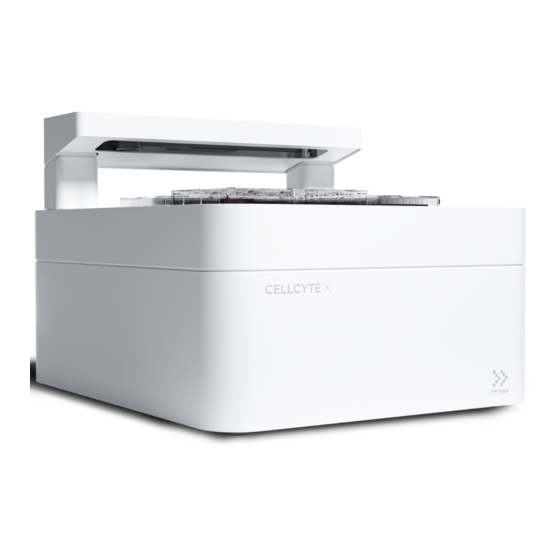
3. Specifications 3.1 Product Figure 1 Product map: CELLCYTE X main unit. CELLCYTE X Main Unit Transmission Unit Objective Lens Vessel Tray 8 | CELLCYTE X... - Page 9 USB-C port DC Power Port Figure 2 CELLCYTE X main unit power port and USB-C port. Figure 3 CELLCYTE X computer unit. CELLCYTE X |...
- Page 10 Figure 4 CELLCYTE X computer unit ports and power switch. Power Switch Power Port C. DC Power Port D. Computer USB ports 1 and 2 Ethernet Output Serial number Figure 5 CELLCYTE X serial number on the backside of the computer unit. The MAC addresses can be found on a sticker at the bottom of the CELLCYTE X computer box.
-
Page 11: Technical Speci Ications
3.2 Technical Specifications Power input: 100–240 VAC, 50–60 Hz, 70 W Fuse: 250 VAC, 1.25 A 3.3 CELLCYTE X Main Unit Height: 334 mm Width: 406 mm Depth: 496 mm Operate the CELLCYTE X microscope unit inside an incubator at a temperature between 20-40 degrees Celsius. -
Page 12: Hardware Setup
4. Hardware Setup 4.1 Contents of the Box • 1x CELLCYTE X Main Unit • 1x CELLCYTE X Computer Unit • 1x 10X Microscope Objective • 1x Power Cord • 1x USB-C Data Cable • 1x DC Power Cable • 1x Ethernet Cable •... - Page 13 Do not attempt to unpack the CELLCYTE X without reviewing the procedure below. Doing so risks personal injury and equipment damage. Clear a stable table and loor space of at least 2 by 3 meters. Place the box on its bottom according to the arrows on the side of the box.
-
Page 14: Manually Cleaning Or Sterilizing The Cellcyte
Remove any remaining packaging material from the CELLCYTE X. Remove the remaining contents of the box and check that you have received all equipment listed in the 4.1 Contents of the box. Either store or recycle the shipping materials. 4.3 Manually Cleaning or Sterilizing the CELLCYTE The CELLCYTE X has a chemical-resistant coating. -
Page 15: Mounting The Objective Lens
4.4 Mounting the Objective Lens First, remove the microscope cap mounted in the optics cube of the main CELLCYTE X unit. Figure 7 Remove microscope cap. Then, proceed to screw in the provided objective lens. Note: The objective lens can be sterilized with ethanol before being mounted into the CELL- CYTE X. -
Page 16: Setting Up Cellcyte X Inside An Incubator
4.5 Setting up CELLCYTE X inside an incubator To set up the CELLCYTE X inside an incubator, follow these steps: Place the CELLCYTE X inside the incubator. Make sure that the transmission bar can move freely inside the incubator. Depending on the dimensions of the incubator, the CELLCYTE X can be placed either with the logo facing out of the incubator (recommended if possible), or with the logo facing sidewards. - Page 17 Connect the CELLCYTE X computer unit’s power outlet (Figure 4) to a grounded wall socket using the included power cord. Always connect the CELLCYTE X to a grounded outlet. Connecting to an ungrounded outlet can cause equipment damage and perso- nal injury.
-
Page 18: Connecting To Cellcyte
5. Connecting to CELLCYTE X 5.1 CELLCYTE X Setup using an existing network While you can work with the CELLCYTE X without using an existing network, the preferred setup is to connect both the CELLCYTE Computer Box and the Laptop/PC(s) running CELLCYTE Studio to the same existing network - prefe- rably via Ethernet. -
Page 19: Netowrk Connection Setup
5.2 Network Connection Setup Again, most important the laptop/PC and the control unit need to be connected to the same (sub) network in order to see each other. If you want to setup via ethernet make sure there is an active ethernet wall port close to the device. There are a lot of different networks out there. - Page 20 Click on the Network icon on the bottom left of your screen and then right click. Choose “Open Network Internet settings”. Figure 12 Figure 13 Open “Network and Sharing Center” Figure 14 20 | CELLCYTE X...
- Page 21 Choose the right network your computer is connected to (in this example it is Ethernet 3). Figure 15 Open “Details...” for the respective network connection. Figure 16 CELLCYTE X |...
- Page 22 Check within the Details if DHCP is enabled for this network connection and the respective IP address you got. Figure 17 If DHCP Enabled is marked as “Yes” can expect a DHCP server to automatically assign IP addresses for your network. 22 | CELLCYTE X...
- Page 23 Setup without using an existing network The simplest setup that does not require any existing network is a point-to- point connection between CELLCYTE Computer Box and the Laptop/PC run- ning CELLCYTE Studio via a dedicated Ethernet cable. However, this setup is limited in allowing only a single Laptop/PC running CELLCYTE Studio at a time.
- Page 24 This setup should give you good transfer speed however you are limited in po- sition to the length of your Ethernet cable and one connected Studio PC at a time. Hint: If your Laptop/PC running CELLCYTE Studio is connected (in addition) to a network that is connected to the internet you can use your DNA cloud user login.
-
Page 25: Getting Started
6. Getting Started System Requirements for laptop/PC We recommend the following computer con igurations for the smooth opera- tion of our software: • OS: Microsoft Windows 10 Operating System (64-bit) • CPU: 2 GHz or faster Intel Core Duo Processor •... -
Page 26: Software Installation And Update
6.2 Software Installation and update The installer ile provided with the product will install one program, CELLCYTE Studio. The respective icon is represented in Figure 13. Figure 20 CELLCYTE Studio icon. Note: Please verify that you have installed the latest version of the software. The latest version of CELLCYTE Studio can be downloaded from https://dna. -
Page 27: Initial Setup In Cellcyte Studio
6.3 Initial Setup in CELLCYTE Studio Double click on the icon to launch CELLCYTE Studio. When starting CELLCYTE Studio for the irst time, you will be asked to complete the initial setup in 4 steps. The initial setup can also be skipped and done later via the settings page. STEP 1. - Page 28 STEP 2. Provide network credentials (if needed) If the CELLCYTE X is connected to the network via ethernet (using an existing network), and your laptop/PC is connected to the same work via ethernet or WiFi, the connection between CELLCYTE Studio and CELLCYTE X will be esta- blished automatically and you can proceed directly to STEP 3.
- Page 29 When you have successfully connected to CELLCYTE X, a green tick mark will appear next to your CELLCYTE X on screen (Figure 23). Figure 23 Successful connection to CELLCYTE X. STEP 3. Select system orientation Select the orientation of your CELLCYTE X system in the incubator (Figure 24). This selection affects how the vessel tray is displayed on the home screen.
- Page 30 STEP 4. Select objective The system comes with a 10X objective (Figure 25). Con irm the selection and proceed. Figure 25 Select the objective magni ication (10X). Once the initial setup is completed, you will be directed to the home screen (re- fer to the user manual for more information).
- Page 31 7. Understanding the CELLCYTE X Status Light The CELLCYTE X computer unit includes an LED status light that indicates different modes of operation (Figure 26). Breathing white CELLCYTE X trying to connect to network. CONNECTING CELLCYTE X ready to image. Solid White READY No scan scheduled (empty timeline).
- Page 32 Discover Echo, Inc. support@discover-echo.com www.discover-echo.com...
Need help?
Do you have a question about the ECHO CELLCYTE X and is the answer not in the manual?
Questions and answers