
Related Manuals for Olimpia splendid B0969


Summary of Contents for Olimpia splendid B0969
- Page 1 Kit B0969 LCAC MANUALE D’USO USER MANUAL MANUEL DE L’UTILISATEUR BETRIEBSANLEITUNG MANUAL DE USO MANUAL DE USO GEBRUIKERSHANDLEIDING...
-
Page 3: Table Of Contents
INDICE GENERALE 1- AVVERTENZE PER LA SICUREZZA .........4 2- PREPARAZIONE ALL’INSTALLAZIONE ......5 3- METODO DI INSTALLAZIONE ...........6 4- DATI TECNICI ..............12 5- CARATTERISTICHE E FUNZIONI DEL COMANDO A MURO ............13 6- DISPLAY LCD DEL COMANDO A MURO ......14 7- PULSANTI SUL COMANDO A MURO......15 8- PREPARAZIONE AL FUNZIONAMENTO......16 9- FUNZIONAMENTO ............17 10- FUNZIONI TIMER .............20... -
Page 4: 1- Avvertenze Per La Sicurezza
1- AVVERTENZE PER LA SICUREZZA - Leggere le avvertenze per la sicurezza prima di installare l’unità. - Le avvertenze indicate sotto sono importanti e devono essere sempre rispettate. AVVERTENZA: Indica un pericolo derivante da una gestione non corretta dell’unità che potrebbe causare infortuni gravi o persino la morte. -
Page 5: 2- Preparazione All'installazione
fughe di elettricità o calore e causare un incendio. - I cavi indicati devono essere utilizzati per il cablag- gio. Nessuna forza esterna deve essere applicata al morsetto. Ciò potrebbe portare al taglio o il riscaldamento del cavo, causando un incendio. 2- PREPARAZIONE ALL’INSTALLAZIONE - Non installare in un luogo ricco di combustibile pesante, vapore o gas solforici per evitare la deformazione del prodotto che porterebbe ad un... -
Page 6: 3- Metodo Di Installazione
- Preparare i seguenti insiemi nel luogo di installazione. Nome Qtà. Note Scatola di commutazione Tubo di collegamento (Manicotto isolante e vite di serraggio) Precauzioni per l’installazione del comando a muro - Questo manuale fornisce il metodo di installazione del comando a muro. Fare riferimento allo schema elettrico di questo manuale di installazione per cablare il comando a muro con l’unità... - Page 7 Schema del principio di collegamento Applicabile solo a KJR- Inserto della scheda 120C1/BTF-E madre CN40 rosso rosso nero nero giallo giallo marrone marrone Cavo schermato a 4 Poli, Scheda madre unità Comando a muro la lunghezza è decisa in interna base all’installazione Inserto della scatola Applicabile solo a KJR-...
- Page 8 Figura raffigurante il cablaggio • Collegare il giunto femmina del gruppo di cavi provenienti dalla scheda madre al giunto maschio del gruppo dei cavi di collegamento. • Si prega di collegare l’altro lato dei cavi di collegamento con il giunto maschio del gruppo di cavi provenienti dal comando a muro.
- Page 9 3. INSTALLATION METHOD Fissaggio della piastra posteriore del comando a muro 5. Fasten the back plate of the wire controller 3. INSTALLATION METHOD • Per il montaggio a vista, fissare la piastra posteriore sul muro con le 3 viti (M4×20) e tasselli. For exposed mounting, fasten the back plate on the wall with the 3 screws (M4×20) 5.
- Page 10 6. Battery installation Installazione della batteria • Posizionare la batteria nel sito di installazione ed assicurarsi che il lato positivo della bat- teria sia conforme al lato positivo del sito di installazione. • Correggere l’ora al primo utilizzo. Le batterie all’interno del comando a muro continuano a funzionare in caso di interruzione di corrente, assicurando di mantenere l’orario corretto.
- Page 11 B.Shielded wiring There are three need cutting. b. Cablaggio schermato Embedded switch Wiring through the wall box wiring Cutting place of right Cutting place of left Cutting place of top side wire outlet side wire outlet side wire outlet Foro cablaggio Foro del muro e foro del cablaggio Wiring Wall hole and wiring hole...
-
Page 12: 4- Dati Tecnici
After adjusting the upper case and then buckle the upper case; avoid clamping the Ricollegare la parte superiore del comando a muro wiring during installation. ( Fig 3-1 1) • Dopo aver regolato e quindi serrato la copertura superiore; evitare di stringere il cablaggio durante l’installazione. -
Page 13: 5- Caratteristiche E Funzioni Del Comando A Muro
5. FEATURE AND FUNCTION OF T CONTROLLER 5- CARATTERISTICHE E FUNZIONI DEL COMAN- DO A MURO POWER MODE FAN SPEED TIMER SWING SWING FOLLOW ME Caratteristiche: DELAY/DAY OFF CONFIRM BACK COPY Display LCD. Dimensioni: H×W×D (mm) 122×120×18.5 Dimension: Visualizzazione codice di errore. H×W×D(mm) 122×120×18.5 Design con filo a 4 vie, nessuna parte rialzata posteriore, facilita il posizionamento dei fili e l’installazione del dispositivo. -
Page 14: 6- Display Lcd Del Comando A Muro
6- DISPLAY LCD DEL COMANDO A MURO 6. NAME ON THE LCD OF THE WIRE CONTROLER 1 Operation mode indication 8 Temperature display 1 Modalità di funzionamento C° / F° 2 Fan speed indication 9 Lock indication 2 Velocità ventilatore 8 Display temperatura 3 Left-right swing indication 10 Room temperature indication... -
Page 15: 7- Pulsanti Sul Comando A Muro
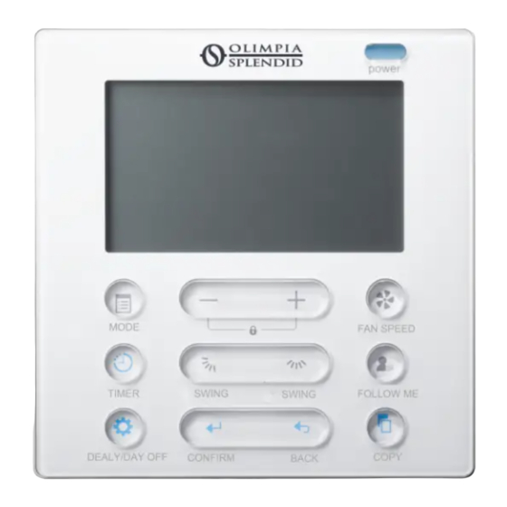
7- PULSANTI SUL COMANDO A MURO 7. NAME OF THE BUTTON ON THE WIRE CONTROLER POWER MODE FAN SPEED TIMER SWING SWING FOLLOW ME DELAY/DAY OFF CONFIRM BACK COPY 1 Pulsante POWER 8 Pulsante TIMER 2 Pulsante MODE 9 Pulsante DELAY/DAY OFF 3 Pulsante regolazione 10 Pulsante CONFIRM 4 Pulsante FAN SPEED... -
Page 16: 8- Preparazione Al Funzionamento
8- PREPARAZIONE AL FUNZIONAMENTO 8. PREPARATORY OPERATION Configurare data e orario corrente Set the current day and time Premere il pulsante TIMER per 3 secondi o più. Press the TIMER button for 3 seconds or more. Il display del timer lampeggia. The timer display will ash. -
Page 17: 9- Funzionamento
9- FUNZIONAMENTO 9. OPERATION 9. OPERATION 9. OPERATION Funzione ricezione segnale remoto Remote signal receiving function Remote signal receiving function Il comando a muro può funzionare come dispositivo di ricezione di un segnale Remote signal receiving function remoto, è possibile utilizzare il comando a muro wireless per controllare il con- The wired remote controller can be a remote signal receiving device, you can use the The wired remote controller can be a remote signal receiving device, you can use the The wired remote controller can be a remote signal receiving device, you can use the... - Page 18 Indoor Unit Press the FAN SPEED button to set the fan speed. (This button is unavailable when in the mode of Auto or Dry) Selezione sensore temperatura ambiente FAN SPEED Room temperature sensor selection Room temperature sensor selection Premere il pulsante FOLLOW ME per Indoor Unit Indoor Unit selezionare se la temperature ambiente...
- Page 19 9. OPERATION 9. OPERATION the child lock function and lock all buttons on the wire controller. 9. OPERATION To set the operation mode Press the buttons again for 3 seconds to deactivate the child lock function. Child lock function 9. OPERATION Funzione Faceplate (non attiva) Operation mode setting Faceplate function (on some models)
-
Page 20: 10- Funzioni Timer
9. OPERATION to all the models) the child lock function and lock all buttons on the wire controller. 2.Press and hold the button for 2 seconds,it turns into up-down swing mode, Press the button “BACK” and “COPY” simultaneously for 3 seconds to press ti again to stop. - Page 21 10. TIMER FUNCTIONS Use t 10. TIMER FUNCTIONS Use this timer fu and a To set the On or Off TIMER Per impostare il TIMER On o Off To set the On or Off TIMER To set the On or Off TIMER Press the TIMER button to select the On timer O tim...
-
Page 22: 11- Timer Settimanale
CONFIRM CONFIRM Premere il pulsante “ + ” o “ - ” per impostare l’ora del timer On, quindi Press the button “ + ” or “ - ” to set the time of On timer,and then press the premere il pulsante CONFIRM per confermare l’impostazione. CONFIRM button to con rm the setting. - Page 23 11. WEEKLY TIMER 11. WEEKLY TIMER To set the On or Off TIMER Press the TIMER button to select the es. Scala temporale 1 di TIMER No display Martedì 10. TIMER FUNCTIONS ex.Tuesday time scale 1 Possono essere salvate fino a 4 impostazioni del timer per ogni giorno della settimana. E’ van- ex.Tuesday time scale 1 To set the On or Off TIMER taggioso se il TIMER SETTIMANALE viene impostato secondo lo stile di vita dell’utilizzatore.
- Page 24 To deactivate WEEKLY TIMER operation Press the TIMER button while is disappear from the LCD. TIMER Press the TIMER button while is disappear from the LCD. 8.Spegnere il condizionare durante il timer settimanale TIMER ● To turn off the air conditioner during the weekly timer Se il pulsante POWER viene premuto una volta velocemente, il con- To turn off the air conditioner during the weekly timer 1.
- Page 25 NOTA • L’impostazione DAY OFF viene automaticamente cancellata dopo che il giorno impostato è passato. • Per eliminare: Seguire gli stessi procedimenti utilizzati per la configurazione. 11. WEEKLY TIMER 11. WEEKLY TIMER DELAY function During the weekly timer, pressing the DELAY button once,display " ".
-
Page 26: 12- Impostazione Pressione Statica Esterna
shown on the LCD. COPY Premere il pulsante “ + ” o “ - ” per selezionare il Press the button “ + ” or “ - ” to select the day giorno da cui copiare. to copy to. Premere il pulsante COPY per confermare. Press the COPY button to con rm . - Page 27 2. SET EXTERNAL STATIC PRESSURE ck that both power supply wiring and duct installation have been completed Check that • You can use the unit’s automatic air ow adjustment function to set external static pressure. closing dampers are open. • Automatic air ow adjustment is the volume of blow-o air that has been automatically •...
-
Page 28: 13- Gestione Allarmi Guasto
13- GESTIONE ALLARMI GUASTO Se il sistema non funziona correttamente, eccetto nei casi sopracitati ed in caso di malfunzionamenti evidenti, controllare il sistema secondo le procedure sotto indicate. CODICE DI NO. MALFUNZIONAMENTO ERRORE Errore di comunicazione tra il coman- do a muro e l’unità interna Controllare il codice di errore che compare sul display dell’unità... - Page 29 MAIN INDEX 1- SAFETY PRECAUTION ............4 2- INSTALLATION ACCESSORY ..........5 3- INSTALLATION METHOD...........6 4- SPECIFICATION ...............12 5- FEATURE AND FUNCTION OF THE WIRED CONTROLLER .............13 6- NAME ON THE LCD OF THE WIRE CONTROLLER ..14 7- NAME OF THE BUTTON ON THE WIRE CONTROLLER ............15 8- PREPARATORY OPERATION ..........16 9- OPERATION ..............17...
- Page 30 1- SAFETY PRECAUTION - Read the safety precautions carefully before installing the unit. - Stated below are important safety issues that must be obeyed. WARNING: Means improper handling may lead to personal death or severe injury. _ _ _ _ _ _ _ _ _ _ _ _ _ _ _ _ _ _ _ _ _ _ _ _ _ _ _ _ _ _ CAUTION: Means improper handling may lead to personal injury or property loss.
- Page 31 No external force may be applied to the terminal. Otherwise, wire cut and heating may occur and result in fire. 2- INSTALLATION ACCESSORY - Don’t install at the place where cover with heavy oil, vapour or sulfurated gas, otherwise, this product would be deformed that would lead to system malfunction.
- Page 32 - Prepare the following assemblies on the site. Name Qty. Remarks Switch box Wiring Tube(Insulating Sleeve and Tightening Screw) Precaution of install the wire controller - This manual provides the installation method of wire controller. Please refer to the wiring diagram of this installation manual to wire the wire controller with indoor unit.
- Page 33 Wiring Principle Sketch Applicable to KJR-120C1/ Insert of the BTF-E only mainboard CN40 black black yellow yellow brown brown 4-Core Shield Cable, Wire controller Indoor unit mainboard the length is decided by installation Insert of the Mul- Applicable to KJR-120C1/ ti-function TF-E only control box CN5...
- Page 34 Wiring figure • Connect the female joint of wires group from the mainboard with the male joint of connective wires group. • Please connect the other side of connective wires group with the male joint of wires group leads from wire controller. .
- Page 35 3. INSTALLATION METHOD Fasten the back plate of the wire controller 5. Fasten the back plate of the wire controller 3. INSTALLATION METHOD • For exposed mounting, fasten the back plate on the wall with the 3 screws (M4×20) and plugs. For exposed mounting, fasten the back plate on the wall with the 3 screws (M4×20) 5.
- Page 36 6. Battery installation Battery installation • Put the battery into the installation site and make sure the positive side of the battery is in accordance with the positive side of installation site. • Please set the time corrected on the first time operation. Batteries in the wire controller can timing under power failure which ensure the time keep right.
- Page 37 B.Shielded wiring There are three need cutting. b. Shielded wiring Embedded switch Wiring through the wall box wiring Cutting place of right Cutting place of left Cutting place of top side wire outlet side wire outlet side wire outlet Wiring hole Wall hole and wiring hole Wiring Wall hole and wiring hole...
- Page 38 After adjusting the upper case and then buckle the upper case; avoid clamping the Reattach the upper part of the wire controller wiring during installation. ( Fig 3-1 1) • After adjusting the upper case and then buckle the upper case; avoid clamping the wiring during installation.
- Page 39 5. FEATURE AND FUNCTION OF T CONTROLLER 5- FEATURE AND FUNCTION OF THE WIRED CON- TROLLER POWER MODE FAN SPEED TIMER SWING SWING FOLLOW ME DELAY/DAY OFF CONFIRM BACK COPY Feature: LCD display. Dimension: Dimension: H×W×D (mm) 122×120×18.5 H×W×D(mm) 122×120×18.5 Malfunction code display.
- Page 40 6- NAME ON THE LCD OF THE WIRE CONTROLLER 6. NAME ON THE LCD OF THE WIRE CONTROLER 1 Operation mode indication 8 Temperature display 1 Operation mode indication 8 Temperature display 2 Fan speed indication 9 Lock indication 2 Fan speed indication 9 Lock indication 3 Left-right swing indication 10 Room temperature indication...
- Page 41 7- NAME OF THE BUTTON ON THE WIRE CON- 7. NAME OF THE BUTTON ON THE WIRE CONTROLER TROLLER POWER MODE FAN SPEED TIMER SWING SWING FOLLOW ME DELAY/DAY OFF CONFIRM BACK COPY 1 POWER button 8 TIMER button 2 MODE button 9 DELAY/DAY OFF button 3 Adjust button 10 CONFIRM button...
- Page 42 8- PREPARATORY OPERATION 8. PREPARATORY OPERATION Set the current day and time Set the current day and time Press the TIMER button for 3 seconds or more. Press the TIMER button for 3 seconds or more. The timer display will ash. The timer display will ash.
- Page 43 9- OPERATION 9. OPERATION 9. OPERATION 9. OPERATION Remote signal receiving function Remote signal receiving function Remote signal receiving function The wired remote controller can be a remote signal receiving device, you Remote signal receiving function can use the wireless remote controller to control the air-conditioner through The wired remote controller can be a remote signal receiving device, you can use the The wired remote controller can be a remote signal receiving device, you can use the The wired remote controller can be a remote signal receiving device, you can use the...
- Page 44 Indoor Unit Press the FAN SPEED button to set the fan speed. (This button is unavailable when in the mode of Auto or Dry) Room temperature sensor selection FAN SPEED Room temperature sensor selection Room temperature sensor selection Press the FOLLOW ME button to select Indoor Unit Indoor Unit whether the room temperature is detected...
- Page 45 PERATION 9. OPERATION d lock function and lock all buttons on the wire controller. 9. OPERATION To set the operation mode e buttons again for 3 seconds to deactivate the child lock function. d lock function 9. OPERATION Faceplate function (not active) Press the button “+”...
- Page 46 9. OPERATION the child lock function and lock all buttons on the wire controller. se the keypad tone. 2.Press and hold the button for 2 seconds,it turns into up-down swing mode, Y ” d “ K ” n “ to all the models) Press the buttons again for 3 seconds to deactivate the child lock function.
- Page 47 10. TIMER FUNCTIONS Use thi 10. TIMER FUNCTIONS Use this timer funct and air To set the On or Off TIMER To set the On or Off TIMER To set the On or Off TIMER To set the On or Off TIMER Press the TIMER button to select the On timer O tim...
- Page 48 CONFIRM CONFIRM Press the button “ + ” or “ - ” to set the time of On timer,and then press the Press the button “ + ” or “ - ” to set the time of On timer,and then press the CONFIRM button to confirm the setting.
- Page 49 11. WEEKLY TIMER 11. WEEKLY TIMER To set the On or Off TIMER Press the TIMER button to select the ex. Tuesday time scale 1 TIMER No display 10. TIMER FUNCTIONS ex.Tuesday time scale 1 Up to 4 timer settings can be saved for each day of the week. It is convenient ex.Tuesday time scale 1 To set the On or Off TIMER if the WEEKLY TIMER is set according to the user’s life style.
- Page 50 To deactivate WEEKLY TIMER operation Press the TIMER button while is disappear from the LCD. TIMER Press the TIMER button while is disappear from the LCD. 8.To turn off the air conditioner during the weekly timer TIMER ● To turn off the air conditioner during the weekly timer If press the POWER button once and quickly , the air To turn off the air conditioner during the weekly timer 1.
- Page 51 NOTE • The DAY OFF setting is cancelled automatically after the set day has passed. • To cancel: Follow the same procedures as those for setup. 11. WEEKLY TIMER 11. WEEKLY TIMER DELAY function 11. WEEKLY TIMER During the weekly timer, pressing the DELAY button once,display " ".
- Page 52 shown on the LCD. COPY Press the button “ + ” or “ - ” to select the day Press the button “ + ” or “ - ” to select the day to copy to. to copy to. Press the COPY button to confirm. Press the COPY button to con rm .
- Page 53 2. SET EXTERNAL STATIC PRESSURE ck that both power supply wiring and duct installation have been completed Check that • You can use the unit’s automatic air ow adjustment function to set external static pressure. closing dampers are open. • Automatic air ow adjustment is the volume of blow-o air that has been automatically • Set the parameters for automatic airflow adjustment. When the air ck that the air lter is properly attached to the air suction side passage of the unit.
- Page 54 13- FAULT ALARM HANDING If the system does not properly operate except the above mentioned cases or the above mentioned malfunctions is evident, investigate the system according to the following procedures. MALFUNCTION & DISPLAY PROTECTION DEFINE DIGITAL TUBE Error of communication between wire controller and indoor unit Please check the error display of indoor unit and read “Instruction manual”...
- Page 55 SOMMAIRE 1- PRÉCAUTIONS DE SÉCURITÉ ..........4 2- ACCESSOIRES D’INSTALLATION ........5 3- MÉTHODE D’INSTALLATION..........6 4- SPÉCIFICATION ...............12 5- CARACTÉRISTIQUES ET FONCTIONS DU CONTRÔLEUR CÂBLÉ ..........13 6- NOM SUR L’ÉCRAN LCD DU CONTRÔLEUR CÂBLÉ ...14 7- NOM DU BOUTON SUR LE CONTRÔLEUR CÂBLÉ ............15 8- OPÉRATION DE PRÉPARATION ........16 9- OPÉRATION ..............17 10- FONCTIONS DE MINUTERIE ..........20...
-
Page 56: 1- Précautions De Sécurité
1- PRÉCAUTIONS DE SÉCURITÉ - Lisez attentivement les consignes de sécurité avant d’installer l’appareil. - Vous trouverez ci-dessous d’importantes questions de sécurité auxquelles il faut se conformer. AVERTISSEMENT: Une manipulation inappropriée peut entraîner la mort ou des blessures graves. _ _ _ _ _ _ _ _ _ _ _ _ _ _ _ _ _ _ _ _ _ _ _ _ _ _ _ _ _ _ ATTENTION: Une manipulation inappropriée peut entraîner des blessures ou des pertes matérielles. -
Page 57: 2- Accessoires D'installation
ment peuvent se produire et provoquer un incendie. - Les câbles spécifiés doivent être appliqué lors du câblage. Aucune force extérieure ne peut être appliquée à la borne. Sinon, une coupure de fil et un échauffement peuvent se produire et provoquer un incendie. 2- ACCESSOIRES D’INSTALLATION - N’installez pas l’appareil à un endroit recouvert d’huile lourde, de vapeur ou de gaz sulfureux ;... -
Page 58: 3- Méthode D'installation
- Préparer les composants suivants sur site. N° Désignation Qté. Remarques Boîte de commutation Tube de câblage (gaine d’isole- ment et vis de serrage) Précaution pour l’installation du contrôleur câblé - Ce manuel fournit la méthode d’installation du contrôleur câblé. Veuillez vous référer au schéma de câblage dans ce manuel d’installation pour connecter le contrôleur câblé... - Page 59 Schéma du principe de câblage Applicable au KJR-120C1/ Insertion de la carte BTF-E uniquement. mère CN40 rouge rouge noir noir jaune jaune marron marron Câble blindé à 4 conduc- Carte mère de l’unité Contrôleur câblé teurs, la longueur est dé- intérieure terminée par l’installation.
- Page 60 Figure du câblage • Connectez le joint femelle du groupe de fils de la carte mère avec le joint mâle du groupe de fils de connexion. • Veuillez connecter l’autre côté du groupe de fils de connexion avec le joint mâle des fils du groupe de fils du contrôleur câblé. .
- Page 61 3. INSTALLATION METHOD Fixer la plaque arrière du contrôleur câblé 5. Fasten the back plate of the wire controller 3. INSTALLATION METHOD • Pour un montage apparent, fixez la plaque arrière au mur avec 3 vis (M4×20) et les chevilles. For exposed mounting, fasten the back plate on the wall with the 3 screws (M4×20) 5.
- Page 62 6. Battery installation Installation de la batterie • Mettez la batterie sur le site d’installation et assu- rez-vous que le côté positif de la batterie est en accord avec le côté positif du site d’installation. • Veuillez régler l’heure corrigée lors de la pre- mière utilisation.
- Page 63 B.Shielded wiring There are three need cutting. b. Câblage blindé Embedded switch Wiring through the wall box wiring Cutting place of right Cutting place of left Cutting place of top side wire outlet side wire outlet side wire outlet Trou de câblage Trou mural et trou de câblage Wiring Wall hole and wiring hole...
-
Page 64: 4- Spécification
After adjusting the upper case and then buckle the upper case; avoid clamping the Fixer à nouveau la partie supérieure du contrôleur câblé wiring during installation. ( Fig 3-1 1) • Après avoir réglé l’étui supérieur, bouclez ce dernier ; évitez de serrer le câblage pendant l’installation. -
Page 65: 5- Caractéristiques Et Fonctions Du Contrôleur Câblé
5. FEATURE AND FUNCTION OF T CONTROLLER 5- CARACTÉRISTIQUES ET FONCTIONS DU CONTRÔLEUR CÂBLÉ POWER MODE FAN SPEED TIMER SWING SWING FOLLOW ME DELAY/DAY OFF CONFIRM BACK COPY Caractéristiques: Affichage LCD. Dimension: H×W×D (mm) 122×120×18.5 Dimension: Affichage du code d’erreur. H×W×D(mm) 122×120×18.5 Conception de la disposition des câbles à... - Page 66 6- NOM SUR L’ÉCRAN LCD DU CONTRÔLEUR CÂBLÉ 6. NAME ON THE LCD OF THE WIRE CONTROLER 1 Operation mode indication 8 Temperature display 1 Indication du mode de fonc- 6 Indication de la fonction Sui- 2 Fan speed indication 9 Lock indication tionnement vez-moi...
-
Page 67: 7- Nom Du Bouton Sur Le Contrôleur Câblé
7- NOM DU BOUTON SUR LE CONTRÔLEUR CÂ- 7. NAME OF THE BUTTON ON THE WIRE CONTROLER BLÉ POWER MODE FAN SPEED TIMER SWING SWING FOLLOW ME DELAY/DAY OFF CONFIRM BACK COPY 1 Bouton POWER (ALIMENTA- 7 Bouton FOLLOW ME (SUI- TION) VEZ-MOI) 2 Bouton MODE (MODE) -
Page 68: 8- Opération De Préparation
8- OPÉRATION DE PRÉPARATION 8. PREPARATORY OPERATION Réglez le jour et l’heure actuels Set the current day and time Appuyez sur le bouton TIMER pendant 3 secondes ou Press the TIMER button for 3 seconds or more. plus. L’affichage de la minuterie clignote. The timer display will ash. -
Page 69: 9- Opération
9- OPÉRATION 9. OPERATION 9. OPERATION 9. OPERATION Fonction de réception du signal à distance Remote signal receiving function Remote signal receiving function La télécommande câblée peut être un dispositif de réception du signaux à Remote signal receiving function distance, vous pouvez utiliser la télécommande sans fil pour contrôler le clima- The wired remote controller can be a remote signal receiving device, you can use the The wired remote controller can be a remote signal receiving device, you can use the The wired remote controller can be a remote signal receiving device, you can use the... - Page 70 Indoor Unit Press the FAN SPEED button to set the fan speed. (This button is unavailable when in the mode of Auto or Dry) Sélection du capteur de température ambiante FAN SPEED Room temperature sensor selection Room temperature sensor selection Appuyez sur le bouton FOLLOW ME pour Indoor Unit Indoor Unit...
- Page 71 9. OPERATION 9. OPERATION 9. OPERATION To set the operation mode the child lock function and lock all buttons on the wire controller. 9. OPERATION Press the buttons again for 3 seconds to deactivate the child lock function. Fonction plastron (non actif) Operation mode setting Child lock function Faceplate function (on some models)
-
Page 72: 10- Fonctions De Minuterie
9. OPERATION close the keypad tone. 2.Press and hold the button for 2 seconds,it turns into up-down swing mode, Y ” d “ to all the models) Press the buttons again for 3 seconds to deactivate the child lock function. Press the buttons again for 3 seconds to open the keypad tone. - Page 73 On timer 10. TIMER FUNCTIONS 10. TIMER FUNCTIONS Use this timer function to start air conditioner operation.The To set the On or Off TIMER and air conditioner operation starts after the time has passed Pour régler la minuterie marche ou arrêt To set the On or Off TIMER To set the On or Off TIMER On t...
-
Page 74: 11- Weekly Minuterie
CONFIRM CONFIRM Appuyez sur le bouton « + » ou « - » pour régler l’heure de la minuterie Press the button “ + ” or “ - ” to set the time of On timer,and then press the marche, puis appuyez sur le bouton CONFIRM pour confirmer le réglage. CONFIRM button to con rm the setting. - Page 75 11. WEEKLY TIMER 11. WEEKLY TIMER To set the On or Off TIMER Press the TIMER button to select the ex.Mardi échelle de temps 1 TIMER No display 10. TIMER FUNCTIONS Jusqu’à 4 réglages de minuterie peuvent être enregistrés pour chaque jour ex.Tuesday time scale 1 ex.Tuesday time scale 1 To set the On or Off TIMER...
- Page 76 To deactivate WEEKLY TIMER operation Press the TIMER button while is disappear from the LCD. TIMER Press the TIMER button while is disappear from the LCD. 8.Pour éteindre le climatiseur pendant la minuterie hebdomadaire TIMER ● To turn off the air conditioner during the weekly timer Si vous appuyez une fois et rapidement sur le bouton POWER, le climatiseur s’éteint temporairement.
- Page 77 REMARQUE • Pour annuler :suivez les mêmes procédures que celles de la configuration. • Le réglage DAY OFF est annulé automatiquement si le jour défini est passé. 11. WEEKLY TIMER 11. WEEKLY TIMER DELAY function 11. WEEKLY TIMER During the weekly timer, pressing the DELA 10.
-
Page 78: 12- Pression Statique Externe Réglée
shown on the LCD. COPY Press the button “ + ” or “ - ” to select the day Appuyez sur le bouton « + » ou « - » pour sélec- to copy to. tionner le jour à copier. Appuyez sur le bouton COPY pour confirmer. - Page 79 2. SET EXTERNAL STATIC PRESSURE ck that both power supply wiring and duct installation have been completed Check that • You can use the unit’s automatic air ow adjustment function to set external static pressure. closing dampers are open. • Automatic air ow adjustment is the volume of blow-o air that has been automatically •...
-
Page 80: 13- Traitement De L'alarme De Défaut
13- TRAITEMENT DE L’ALARME DE DÉFAUT Si le système ne fonctionne pas correctement à l’exception des cas men- tionnés ci-dessus ou si les dysfonctionnements mentionnés ci-dessus sont évidents, examinez le système selon les procédures suivantes. DÉFINITION DU TUBE N° DYSFONCTIONNEMENT ET D’AFFICHAGE DE LA PROTECTION NUMÉRIQUE... - Page 81 HAUPTVERZEICHNIS 1- SICHERHEITSVORKEHRUNGEN ........4 2- INSTALLATIONSZUBEHÖR ..........5 3- INSTALLATIONSVERFAHREN ..........6 4- SPEZIFIKATIONEN ............12 5- MERKMALE UND FUNKTIONEN DES KABELGEBUNDE- NEN REGLERS ..............13 6- BENENNUNGEN AUF DER LCD DES KABELGEBUNDENEN REGLERS .................14 7- BENENNUNG DER TASTEN DES KABELGEBUNDENEN REGLERS .................15 8- VORBEREITENDE MASSNAHMEN .........16 9- BETRIEB ................17 10- TIMER-FUNKTIONEN ............20 11- WOCHENTIMER ...............22...
-
Page 82: 1- Sicherheitsvorkehrungen
1- SICHERHEITSVORKEHRUNGEN - Die Sicherheitsvorkehrungen vor der Installation der Einheit sorgfältig durchlesen. - Nachfolgend werden wichtige Sicherheitshinweise gegeben, die eingehalten werden müssen. ACHTUNG: Bedeutet, dass eine unsachgemäße Hand- habung zum Tod oder zu schweren Verletzungen von Personen führen kann. _ _ _ _ _ _ _ _ _ _ _ _ _ _ _ _ _ _ _ _ _ _ _ _ _ _ _ _ _ _ VORSICHT: Bedeutet, dass eine unsachgemäße Hand- habung zu Verletzungen oder Sachschäden führen kann. - Page 83 und einen Brand verursachen. - Die angegebenen Kabel für die Verkabelung verwenden. Keine externe Krafteinwirkung auf das Terminal ausüben. Anderenfalls können die Drähte beschädigt werden, das Gerät könnte sich aufheizen und einen Brand verursachen. 2- INSTALLATIONSZUBEHÖR - Das Gerät nicht an einem Ort installieren, an dem Schweröle, Dämpfe oder schwefelhaltige Gase auftreten, da dieses Produkt sonst verformt wird, was zu einer Störung des Systems führt.
-
Page 84: 3- Installationsverfahren
Folgende Baugruppen auf der Baustelle vorbereiten. Bezeichnung Menge Anmerkungen Schaltkasten Verkabelungsleitung (Isolierung und Verschlussschraube) Vorsichtsmaßnahmen bei der Installation des kabelgebundenen Reglers - In diesem Handbuch wird das Installationsverfahren des kabelgebundenen Reglers erläutert. Bei der Verkabelung des Reglers mit dem Innenraumgerät bitte auf den Schaltplan dieser Betriebsanleitung Bezug nehmen. - Page 85 Skizze des Verkabelungsverfahrens Nur bei KJR-120C1/BTF-E Einsatz der anwendbar Hauptplatine CN40 schwarz schwarz gelb gelb braun braun 4-adriges abgeschirmtes Kabel, die Länge wird Kabelgebundener Hauptplatine Innen- durch die Installation Regler raumgerät bestimmt Einsatz der Nur bei KJR-120C1/TF-E Multifunktionssteuerbox anwendbar schwarz schwarz gelb gelb...
- Page 86 Abbildung der Verkabelung • Die Kabelbuchse der Hauptplatine mit dem Stecker des Anschlusses verbinden. • Die andere Seite der Verbindungskabel an das vom kabelgebundenen Regler kommenden Kabel anschließen. . INSTALLATION METHOD Hauptplatine 3.Wiring figure CN40 The connective wires group-1 Mainboard Verbindungska- 4-core shielding wire bel Gruppe-2...
- Page 87 3. INSTALLATION METHOD Die rückseitige Platte des kabelgebundenen Reglers befestigen. 5. Fasten the back plate of the wire controller 3. INSTALLATION METHOD • Bei einer Aufputzmontage, die rückseitige Platte mit 3 Schrauben (M4x20) und Dübeln befestigen. For exposed mounting, fasten the back plate on the wall with the 3 screws (M4×20) 5.
- Page 88 6. Battery installation Installation der Batterie • Die Batterie in das Gehäuse legen und darauf achten, dass der positive Pol von Batterie und Gehäuse übereinstimmen. • Die Zeit bei der ersten Inbetriebnahme richtig einstellen. Bei einem Stromausfall können die Batterien des kabelgebundenen Reglers die richtige Uhrzeit gewährleisten und die Zeitmessung aufrecht halten.
- Page 89 B.Shielded wiring There are three need cutting. b. Abgeschirmte Verkabelung Embedded switch Wiring through the wall box wiring Cutting place of right Cutting place of left Cutting place of top side wire outlet side wire outlet side wire outlet Kabelöffnung Wiring Wandbohrung und Kabelöffnung Wall hole and wiring hole...
-
Page 90: 4- Spezifikationen
After adjusting the upper case and then buckle the upper case; avoid clamping the Den oberen Teil des kabelgebundenen Reglers wieder anbringen. wiring during installation. ( Fig 3-1 1) • Nachdem das obere Gehäuse ausgerichtet wurde, dieses verschließen; bei der Installation das Kabel nicht einklemmen. Fig 3-11 4- SPEZIFIKATIONEN Eingangsspannung... -
Page 91: 5- Merkmale Und Funktionen Des Kabelgebundenen Reglers
5. FEATURE AND FUNCTION OF T CONTROLLER 5- MERKMALE UND FUNKTIONEN DES KABELGEBUNDENEN REGLERS POWER MODE FAN SPEED TIMER SWING SWING FOLLOW ME Merkmal: DELAY/DAY OFF CONFIRM BACK COPY LCD-Bildschirm Abmessungen: H×BxT (mm) 122×120×18,5 Dimension: Anzeige Störungscode. H×W×D(mm) 122×120×18.5 4-Wege Verkabelungslayout, kein hervorstehender Teil auf der Rückseite, die Kabel und das Gerät können einfacher verlegt werden. -
Page 92: 6- Benennungen Auf Der Lcd Des Kabelgebundenen Reglers
6- BENENNUNGEN AUF DER LCD DES 6. NAME ON THE LCD OF THE WIRE CONTROLER KABELGEBUNDENEN REGLERS 1 Operation mode indication 8 Temperature display 1 Anzeige des Betriebsmodus 7 Anzeige C° / F° 2 Fan speed indication 9 Lock indication 2 Anzeige der 8 Temperaturanzeige 3 Left-right swing indication... -
Page 93: 7- Benennung Der Tasten Des Kabelgebundenen Reglers
7- BENENNUNGEN DER TASTEN DES 7. NAME OF THE BUTTON ON THE WIRE CONTROLER KABELGEBUNDENEN REGLERS POWER MODE FAN SPEED TIMER SWING SWING FOLLOW ME DELAY/DAY OFF CONFIRM BACK COPY 1 EINSCHALT-Taste 7 FOLLOW-ME-Taste 2 Taste der Betriebsweise 8 TIMER-Taste 3 Einstelltaste 9 Taste VERZÖGERUNG/TAG AUS 4 Taste der Lüftergeschwindigkeit... -
Page 94: 8- Vorbereitende Massnahmen
8- VORBEREITENDE MASSNAHMEN 8. PREPARATORY OPERATION Aktuelles Datum und Zeit einstellen Set the current day and time Die TIMER-Taste 3 Sekunden lang oder länger drücken. Press the TIMER button for 3 seconds or more. Die Timeranzeige blinkt. The timer display will ash. TIMER Die Taste „+“... -
Page 95: 9- Betrieb
9- BETRIEB 9. OPERATION 9. OPERATION 9. OPERATION Funktion Empfang von Fernsteuersignalen Remote signal receiving function Remote signal receiving function Der kabelgebundene Fernregler kann auch als Empfangsgerät von Remote signal receiving function Fernsteuerungssignalen sein; die kabellose Fernsteuerung kann zur The wired remote controller can be a remote signal receiving device, you can use the The wired remote controller can be a remote signal receiving device, you can use the The wired remote controller can be a remote signal receiving device, you can use the Steuerung eines Klimageräts durch den kabelgebundenen Regler... - Page 96 Indoor Unit Press the FAN SPEED button to set the fan speed. (This button is unavailable when in the mode of Auto or Dry) Auswahl des Raumtemperaturfühlers FAN SPEED Room temperature sensor selection Room temperature sensor selection Die FOLLOW-ME-Taste drücken, um Indoor Unit Indoor Unit zu wählen, ob die Raumtemperatur...
- Page 97 9. OPERATION To set the operation mode . OPERATION 9. OPERATION e button “+” and “-” simultaneously for 3 seconds to activate 9. OPERATION Frontplatten-Funktion (nicht aktiv) Operation mode setting d lock function and lock all buttons on the wire controller. Faceplate function (on some models) e models) Child lock function...
-
Page 98: 10- Timer-Funktionen
9. OPERATION Press the buttons again for 3 seconds to deactivate the child lock function. se the keypad tone. ” 2.Press and hold the button for 2 seconds,it turns into up-down swing mode, to all the models) ss the buttons again for 3 seconds to open the keypad tone. press ti again to stop. - Page 99 10. TIMER FUNCTIONS Use this timer fu 10. TIMER FUNCTIONS Use this timer function to set o and air condition To set the On or Off TIMER Einstellung des On- oder OFF-Timers To set the On or Off TIMER To set the On or Off TIMER Press the TIMER button to select the On timer O timer...
-
Page 100: 11- Wochentimer
CONFIRM CONFIRM Die Taste „+“ oder „-“ drücken, um die Zeit des On-Timers einzustellen, dann Press the button “ + ” or “ - ” to set the time of On timer,and then press the die BESTÄTIGUNGS-Taste drücken, um die Einstellung zu bestätigen. CONFIRM button to con rm the setting. - Page 101 11. WEEKLY TIMER 11. WEEKLY TIMER To set the On or Off TIMER Press the TIMER button to select the TIMER No display z.B. Dienstag Zeitskala 1 10. TIMER FUNCTIONS ex.Tuesday time scale 1 Es können bis zu 4 Einstellungen des Timers für jeden Wochentag ex.Tuesday time scale 1 To set the On or Off TIMER vorgenommen werden.
- Page 102 To deactivate WEEKLY TIMER operation Press the TIMER button while is disappear from the LCD. TIMER Press the TIMER button while is disappear from the LCD. 8.Klimagerät während des Wochentimers ausschalten TIMER ● To turn off the air conditioner during the weekly timer Wird die EINSCHALT-Taste einmal und kurz gedrückt, To turn off the air conditioner during the weekly timer 1.
- Page 103 HINWEIS • Die Einstellung TAG AUS wird automatisch gelöscht, nachdem dieser Tag vorbei ist. • Löschen: Dem gleichen Verfahren folgen wie bei der Einstellung. 11. WEEKLY TIMER 11. WEEKLY TIMER DELAY function 11. WEEKLY TIMER During the weekly timer, pressing the DELAY button once,display " ".
-
Page 104: 12- Externen Statischen Druck Einstellen
shown on the LCD. COPY Press the button “ + ” or “ - ” to select the day Die Taste „+“ oder „-“ drücken, um den Wochentag to copy to. auszuwählen, in den kopiert werden soll. Zur Bestätigung die COPY-Taste drücken. Press the COPY button to con rm . - Page 105 2. SET EXTERNAL STATIC PRESSURE ck that both power supply wiring and duct installation have been completed Check that • You can use the unit’s automatic air ow adjustment function to set external static pressure. closing dampers are open. • Automatic air ow adjustment is the volume of blow-o air that has been automatically •...
-
Page 106: 13- Störungsmeldungen
13- STRÖRUNGSMELDUNGEN Wenn das System mit Ausnahme der oben genannten Fälle nicht richtig funktioniert oder die oben genannten Störungen eindeutig sind, das System gemäß folgendem Verfahren untersuchen. DIGITALE NR. STÖRUNG & SCHUTZ FESTLEGEN ANZEIGE Kommunikationsfehler zwischen kabelgebundenen Regler und Innen- raumgerät Die Fehleranzeige am Innenraumgerät prüfen und die „Betriebsanleitung“... - Page 107 ÍNDICE GENERAL 1- ADVERTENCIAS PARA LA SEGURIDAD ......4 2- PREPARACIÓN A LA INSTALACIÓN ........5 3- MÉTODO DE INSTALACIÓN ..........6 4- DATOS TÉCNICOS ............12 5- CARACTERÍSTICAS Y FUNCIONES DEL MANDO DE MURO ............13 6- PANTALLA LCD DEL MANDO DE MURO .......14 7- PULSADORES EN EL MANDO DE MURO ......15 8- PREPARACIÓN PARA EL FUNCIONAMIENTO ....16 9- FUNCIONAMIENTO ............17...
- Page 108 1- ADVERTENCIAS PARA LA SEGURIDAD - Lea las advertencia para la seguridad antes de instalar la unidad. - Las advertencias indicadas abajo son importantes y siempre deben respetarse. ADVERTENCIA: Índica un peligro que deriva de una gestión incorrecta de la unidad que podría causar lesione graves o incluso la muerte.
- Page 109 electricidad o calor y causar un incendio. - Los cables indicados deben utilizarse para el cableado. Ninguna fuerza externa debe aplicarse a la abrazadera. Esto podría causar el corte o el calentamiento del cable, causando un incendio. 2- PREPARACIÓN A LA INSTALACIÓN - No instale en un lugar rico de combustible pesado, vapor o gases sulfú- ricos para evitar la deformación del producto que podría llevar a un mal funcionamiento del sistema.
- Page 110 - Prepare los montajes siguientes en el lugar de instalación. Nombre Cant. Notas Caja de conexiones Tubo de conexión (Manguito aislante y tornillo de apriete) Precauciones para la instalación del mando a muro - Este manual suministra el método de instalación del mando a muro. Refiérase al esquema eléctrico de este manual de instalación para cablear el mando a muro con la unidad interna.
- Page 111 Esquema del principio de conexión Aplicable sólo a KJR- Inserto de la placa 120C1/BTF-E base CN40 rojo rojo negro negro amarillo amarillo marrón marrón Cable blindado de 4 Polos, Placa base de la Mando de muro la longitud se decide basa- unidad interna do en la instalación Inserto de la caja de Aplicable sólo a KJR- control multifunción...
- Page 112 Figura que muestra el cableado • Conecte la junta hembra del grupo de cables provenientes de la placa base a la junta macha del grupo de cables de conexión. • Conecte el otro lado de los cables de conexión con la junta macha del grupo de cables provenientes del mando de muro.
- Page 113 3. INSTALLATION METHOD Fijación de la placa trasera del mando de muro 5. Fasten the back plate of the wire controller 3. INSTALLATION METHOD • Para el montaje expuesto, fije la placa trasera en el muro con los 3 tornillos (M4×20) y tarugos. For exposed mounting, fasten the back plate on the wall with the 3 screws (M4×20) 5.
- Page 114 6. Battery installation Instalación de la batería • Posicione la batería en el sitio de instalación y asegúrese de que el lado positivo de la batería cumpla con el lado positivo del sitio de instalación. • Corrija la hora al primer uso. Las baterías dentro del mando de muro siguen funcionar en el caso de interrupción de corriente, asegurán- dose de mantener la hora correcta.
- Page 115 B.Shielded wiring There are three need cutting. b. Cableado blindado Embedded switch Wiring through the wall box wiring Cutting place of right Cutting place of left Cutting place of top side wire outlet side wire outlet side wire outlet Agujero cableado Agujero del muro y del cableado Wiring Wall hole and wiring hole...
- Page 116 After adjusting the upper case and then buckle the upper case; avoid clamping the Volver la parte superior del mando de muro wiring during installation. ( Fig 3-1 1) • Después de haber ajustado y entonces apretado la cobertura superior; evite apretar el cableado durante la instalación.
- Page 117 5. FEATURE AND FUNCTION OF T CONTROLLER 5- CARACTERÍSTICAS Y FUNCIONES DEL MANDO DE MURO POWER MODE FAN SPEED TIMER SWING SWING FOLLOW ME Características: DELAY/DAY OFF CONFIRM BACK COPY Pantalla LCD. Dimensiones: H×W×D (mm) 122×120×18.5 Dimension: Visualización del código de error. H×W×D(mm) 122×120×18.5 Diseño con hilo de 4 vías, ninguna parte elevada trasera, facilita el posicionamiento de los hilos y la instalación del dispositivo.
- Page 118 6- PANTALLA LCD DEL MANDO DE MURO 6. NAME ON THE LCD OF THE WIRE CONTROLER 1 Operation mode indication 8 Temperature display 1 Modo de funcionamiento peratura en C° / F° 2 Fan speed indication 9 Lock indication 2 Velocidad del ventilador 8 Pantalla temperatura 3 Left-right swing indication 10 Room temperature indication...
- Page 119 7- PULSADORES EN EL MANDO DE MURO 7. NAME OF THE BUTTON ON THE WIRE CONTROLER POWER MODE FAN SPEED TIMER SWING SWING FOLLOW ME DELAY/DAY OFF CONFIRM BACK COPY 1 Pulsador POWER 8 Pulsador TIMER 2 Pulsador MODE 9 Pulsador DELAY/DAY OFF 3 Pulsador de ajuste 10 Pulsador CONFIRM 4 Pulsador FAN SPEED...
- Page 120 8- PREPARACIÓN PARA EL FUNCIONAMIENTO 8. PREPARATORY OPERATION Configurar fecha y hora corriente Set the current day and time Presione el pulsador TIMER durante 3 segundos o más. Press the TIMER button for 3 seconds or more. La pantalla del temporizador parpadea. The timer display will ash. TIMER Presione el pulsador “...
- Page 121 9- FUNCIONAMIENTO 9. OPERATION 9. OPERATION 9. OPERATION Función de recepción de la señal remota Remote signal receiving function Remote signal receiving function El mando de muro puede funcionar como dispositivo de recepción de una señal Remote signal receiving function remota, es posible utilizar el mando de muro inalámbrico para controlar el acondi- The wired remote controller can be a remote signal receiving device, you can use the The wired remote controller can be a remote signal receiving device, you can use the...
- Page 122 Indoor Unit Press the FAN SPEED button to set the fan speed. (This button is unavailable when in the mode of Auto or Dry) Selección del sensor de la temperatura ambiente FAN SPEED Room temperature sensor selection Room temperature sensor selection Presione el pulsador FOLLOW ME para Indoor Unit Indoor Unit seleccionar si la temperatura ambiente...
- Page 123 Press the button “+” and “-” simultaneously for 3 seconds to activate 9. OPERATION 9. OPERATION To set the operation mode 9. OPERATION the child lock function and lock all buttons on the wire controller. 9. OPERATION Función Faceplate (no activa) Operation mode setting Press the buttons again for 3 seconds to deactivate the child lock function.
- Page 124 9. OPERATION the child lock function and lock all buttons on the wire controller. When the Up-Down swing function is activated,the 2.Press and hold the button for 2 seconds,it turns into up-down swing mode, mark appears. (Not applicable Press the button “BACK” and “COPY” simultaneously for 3 seconds to press ti again to stop.
- Page 125 10. TIMER FUNCTIONS Use t 10. TIMER FUNCTIONS Use this timer fu and a To set the On or Off TIMER Para configurar el TIMER On u Off To set the On or Off TIMER To set the On or Off TIMER Press the TIMER button to select the On timer O ti Presione el pulsador TIMER para seleccionar...
- Page 126 CONFIRM CONFIRM Presione el pulsador “ + ” o “ - ” para configurar la hora del timer On, Press the button “ + ” or “ - ” to set the time of On timer,and then press the entonces presione el pulsador CONFIRM para confirmar la configuración. CONFIRM button to con rm the setting.
- Page 127 11. WEEKLY TIMER 11. WEEKLY TIMER To set the On or Off TIMER Press the TIMER button to select the ej. Escala temporal 1 de TIMER No display Martes 10. TIMER FUNCTIONS ex.Tuesday time scale 1 Se pueden guardar hasta 4 configuraciones del timer para cada día de la semana. ex.Tuesday time scale 1 To set the On or Off TIMER Es ventajoso si el TIMER SEMANAL se configura según el estilo de vida del usuario.
- Page 128 To deactivate WEEKLY TIMER operation Press the TIMER button while is disappear from the LCD. TIMER Press the TIMER button while is disappear from the LCD. 8.Apague el acondicionador durante el temporizador semanal TIMER ● To turn off the air conditioner during the weekly timer Si el pulsador POWER una vez rapidámente, el acondicionador To turn off the air conditioner during the weekly timer 1.
- Page 129 NOTA • La configuración DAY OFF se anula automáticamente después de que el día configurado haya pasado. • Para eliminar: Siga los mismos pasajes utilizados para la configuración. 11. WEEKLY TIMER 11. WEEKLY TIMER DELAY function During the weekly timer, pressing the DELAY button once,display " ".
- Page 130 shown on the LCD. COPY Presione el pulsador “ + ” o “ - ” para seleccionar el Press the button “ + ” or “ - ” to select the day día desde el cual es necesario copiar. to copy to. Presione el pulsador COPY para confirmar.
- Page 131 2. SET EXTERNAL STATIC PRESSURE ck that both power supply wiring and duct installation have been completed Check that • You can use the unit’s automatic air ow adjustment function to set external static pressure. closing dampers are open. • Automatic air ow adjustment is the volume of blow-o air that has been automatically •...
- Page 132 13- GESTIÓN DE LAS ALARMAS DE AVERÍA Si el sistema no funciona correctamente, excepto en los casos des- critos arriba y en el caso de mal funcionamientos evidentes, controle el sistema según los procedimientos indicados abajo. CÓDIGO DE NO. MAL FUNCIONAMIENTO ERROR Error de comunicación entre el man- do de muro y la unidad interna...
- Page 133 ÍNDICE PRINCIPAL 1- PRECAUÇÕES DE SEGURANÇA ........4 2- ACESSÓRIO DE INSTALAÇÃO .........5 3- MÉTODO DE INSTALAÇÃO ..........6 4- ESPECIFICAÇÕES ............12 5- CARACTERÍSTICAS E FUNÇÃO DO CONTROLADOR COM FIOS ................13 6- NOME NO LCD DO CONTROLADOR COM FIOS 14 7- NOME DOS BOTÕES NO CONTROLADOR COM FIOS .15 8- OPERAÇÃO PREPARATÓRIA .........16 9- OPERAÇÃO ..............17 10- FUNÇÕES DO TEMPORIZADOR ........20...
-
Page 134: 1- Precauções De Segurança
1- PRECAUÇÕES DE SEGURANÇA - Leia as precauções de segurança cuidadosamente antes de instalar a unidade. - Abaixo, aparecem indicados os pontos importantes de segurança que devem ser cumpridos. AVISO: Significa que o manuseio inadequado pode levar à morte da pessoa ou ferimentos graves. _ _ _ _ _ _ _ _ _ _ _ _ _ _ _ _ _ _ _ _ _ _ _ _ _ _ _ _ _ _ CUIDADO: Significa que o manuseio inadequado pode levar a ferimentos ou perda de propriedade. - Page 135 perda elétrica ou aquecimento e resultar em incêndio. - Os cabos especificados devem ser aplicados na cablagem. Nenhuma força externa pode ser aplicada ao terminal. Caso contrário, pode ocorrer corte de fio ou aquecimento e resultar em incêndio. 2- INSTALAÇÃO DOS ACESSÓRIOS Não instale em local onde estiver coberto com óleo pesado, vapor ou gás sulfurizado, caso contrário, o produto poderá...
-
Page 136: 3- Método De Instalação
- Prepare os seguintes conjuntos no local. N.° Nome Qtd. Observações Caixa de comutação Tubo de cablagem (manga de isolamento e parafuso de aperto) Precaução para instalar o controlador com fios - Este manual fornece o método de instalação do controlador com fios. Por favor, consulte o diagrama de cablagem deste manual de instalação para instalar o controlador com fios na unidade interna. - Page 137 Esboço princípio de cablagem Aplicável apenas a KJR- Inserção da placa 120C1/BTF-E principal CN40 vermelho vermelho preto preto amarelo amarelo castanho castanho Cabo protetor de 4 Placa principal da Controlador com fios núcleos, o comprimento é unidade interior decidido pela instalação Inserção da caixa de Aplicável apenas a KJR- controlo multifunções...
- Page 138 Figura de cablagem • Conecte a junta fêmea do grupo de fios da placa principal com a junta macho do grupo de fios conectores. • Por favor, conecte o outro lado do grupo de fios conectivos com a junta macho dos cabos do grupo de fios do controlador com fios. .
- Page 139 3. INSTALLATION METHOD Fixe a placa traseira do controlador com fios 5. Fasten the back plate of the wire controller 3. INSTALLATION METHOD • Para montagem exposta, aperte a placa traseira na parede com os 3 parafusos (M4x20) e buchas. For exposed mounting, fasten the back plate on the wall with the 3 screws (M4×20) 5.
- Page 140 6. Battery installation Instalação da bateria • Coloque a bateria no local de instalação e certifique-se de que o lado positivo da bateria esteja de acordo com o lado positivo do local de instalação. • Defina a hora corrigida na primeira operação. As baterias no controlador com fios podem sincronizar com a falha de energia, o que garante que o tempo permaneça correto.
- Page 141 B.Shielded wiring There are three need cutting. b. Cablagem blindada Embedded switch Wiring through the wall box wiring Cutting place of right Cutting place of left Cutting place of top side wire outlet side wire outlet side wire outlet Orifício de Orifício de parede e orifício de cablagem Wiring Wall hole and wiring hole...
-
Page 142: 4- Especificações
After adjusting the upper case and then buckle the upper case; avoid clamping the Recoloque a parte superior do controlador com fios wiring during installation. ( Fig 3-1 1) • Depois de ajustar a caixa superior e depois apertar a caixa superior; evite prender a cablagem durante a instalação. -
Page 143: 5- Características E Função Do Controlador Com Fios
5. FEATURE AND FUNCTION OF T CONTROLLER 5- CARACTERÍSTICAS E FUNÇÃO DO CONTROLADOR COM FIOS POWER MODE FAN SPEED TIMER SWING SWING FOLLOW ME Características: DELAY/DAY OFF CONFIRM BACK COPY Monitor LCD. Dimensões: A×L×P (mm) 122×120×18,5 Dimension: Ecrã código de erro. H×W×D(mm) 122×120×18.5 Design de layout de fio de 4 vias, sem parte levantada na parte traseira, mais conveniente para colocar os fios e instalar o dispositivo. - Page 144 6- NOME NO LCD DO CONTROLADOR COM FIOS 6. NAME ON THE LCD OF THE WIRE CONTROLER 1 Indicação do modo de operação 6 Indicação da função Siga-me 1 Operation mode indication 8 Temperature display 2 Indicação de velocidade do venti- 7 Indicação C°...
-
Page 145: 7- Nome Dos Botões No Controlador Com Fios
7- NOME DOS BOTÕES NO CONTROLADOR COM 7. NAME OF THE BUTTON ON THE WIRE CONTROLER FIOS POWER MODE FAN SPEED TIMER SWING SWING FOLLOW ME DELAY/DAY OFF CONFIRM BACK COPY 1 Botão LIGAR 7 Botão SIGA-ME 2 Botão MODO 8 Botão TEMPORIZADOR 3 Botão ajustar 9 Botão ATRASO/DIA DESLIGADO... -
Page 146: 8- Operação Preparatória
8- OPERAÇÃO PREPARATÓRIA 8. PREPARATORY OPERATION Configurar a data e hora atuais Set the current day and time Pressione o botão TEMPORIZADOR por 3 segundos ou Press the TIMER button for 3 seconds or more. mais. O visor do temporizador irá lampejar. The timer display will ash. -
Page 147: 9- Operação
9- OPERAÇÃO 9. OPERATION 9. OPERATION 9. OPERATION Função do recetor de sinal remoto Remote signal receiving function Remote signal receiving function O controlo remoto com fios pode ser um dispositivo de receção de sinal Remote signal receiving function remoto. Pode usar o controlo remoto sem fios para controlar o ar condicionado The wired remote controller can be a remote signal receiving device, you can use the The wired remote controller can be a remote signal receiving device, you can use the The wired remote controller can be a remote signal receiving device, you can use the... - Page 148 Indoor Unit Press the FAN SPEED button to set the fan speed. (This button is unavailable when in the mode of Auto or Dry) Seleção do sensor de temperatura ambiente FAN SPEED Room temperature sensor selection Room temperature sensor selection Pressione o botão SIGA-ME para Indoor Unit Indoor Unit...
- Page 149 Press the button “+” and “-” simultaneously for 3 seconds to activate 9. OPERATION 9. OPERATION To set the operation mode the child lock function and lock all buttons on the wire controller. 9. OPERATION 9. OPERATION Função placa frontal (não activo) Operation mode setting Press the buttons again for 3 seconds to deactivate the child lock function.
-
Page 150: 10- Funções Do Temporizador
9. OPERATION Press the buttons again for 3 seconds to deactivate the child lock function. close the keypad tone. 2.Press and hold the button for 2 seconds,it turns into up-down swing mode, ” to all the models) Press the buttons again for 3 seconds to open the keypad tone. press ti again to stop. - Page 151 10. TIMER FUNCTIONS Use t 10. TIMER FUNCTIONS Use this timer fu and a To set the On or Off TIMER Para definir o temporizador ligado ou desligado To set the On or Off TIMER To set the On or Off TIMER Press the TIMER button to select the On timer O ti...
-
Page 152: 11- Temporizador Semanal
CONFIRM CONFIRM Pressione o botão “ + ” ou “ - ” para configurar a hora do temporizador e Press the button “ + ” or “ - ” to set the time of On timer,and then press the depois o botão de confirmação para confirmar a configuração. CONFIRM button to con rm the setting. - Page 153 11. WEEKLY TIMER 11. WEEKLY TIMER To set the On or Off TIMER Press the TIMER button to select the ex. Dimensão temporal TIMER No display terça-feira 1 10. TIMER FUNCTIONS ex.Tuesday time scale 1 Até 4 configurações de temporizador podem ser guardadas para cada dia ex.Tuesday time scale 1 To set the On or Off TIMER da semana.
- Page 154 To deactivate WEEKLY TIMER operation Press the TIMER button while is disappear from the LCD. TIMER Press the TIMER button while is disappear from the LCD. 8.Para desligar o ar condicionado durante o temporizador semanal TIMER ● To turn off the air conditioner during the weekly timer Se pressionar o botão LIGAR uma vez e rapidamente, To turn off the air conditioner during the weekly timer 1.
- Page 155 NOTA • A configuração DIA DESLIGADO é cancelada automaticamente após o dia definido. • Para cancelar: Siga os mesmos procedimentos para configuração. 11. WEEKLY TIMER 11. WEEKLY TIMER DELAY function 11. WEEKLY TIMER During the weekly timer, pressing the DELAY button once,display " ".
- Page 156 shown on the LCD. COPY Press the button “ + ” or “ - ” to select the day Pressione o botão “ + ” ou “ - ” para selecionar o to copy to. dia para o qual copiar. Pressione o botão COPIAR para confirmar.
- Page 157 2. SET EXTERNAL STATIC PRESSURE ck that both power supply wiring and duct installation have been completed Check that • You can use the unit’s automatic air ow adjustment function to set external static pressure. closing dampers are open. • Automatic air ow adjustment is the volume of blow-o air that has been automatically •...
-
Page 158: 13- Manuseio Alarme De Falhas
13- MANUSEIO ALARME DE FALHA Se o sistema não funcionar corretamente, exceto nos casos acima mencionados em que as avarias são evidentes, verifique o sistema seguindo os procedimentos abaixo. TUBO DEFINIÇÃO DE MAU FUNCIONA- N.º DIGITAL DE MENTO E PROTEÇÃO VISUALIZAÇÃO Erro de comunicação entre o contro- lador de fio e a unidade interna... - Page 159 INHOUDSOPGAVE 1- VEILIGHEIDSMAATREGELEN ...........4 2- BIJKOMENDE OPMERKING OVER DE INSTALLATIE ..5 3- INSTALLATIEMETHODE ............6 4- SPECIFICATIE ..............12 5- FUNCTIE EN WERKING VAN DE BEDRADE BEDIENING . 6- BENAMING OP LCD VAN DE BEDRADE BEDIENING ...14 7- BENAMING VAN KNOPPEN OP DE BEDRADE BEDIE- NING .................15 8- VOORBEREIDENDE HANDELINGEN ......16 9- WERKING ................17...
-
Page 160: 1- Veiligheidsmaatregelen
1- VEILIGHEIDSMAATREGELEN - Lees zorgvuldig de veiligheidsmaatregelen alvorens de unit te installeren. - Hieronder worden belangrijke veiligheidskwesties vermeld die in acht genomen moeten worden. WAARSCHUWING: Geeft aan dat een verkeerde behandeling tot de dood of ernstig persoonlijk letsel kan leiden. _ _ _ _ _ _ _ _ _ _ _ _ _ _ _ _ _ _ _ _ _ _ _ _ _ _ _ _ _ _ VOORZICHTIG: Geeft aan dat een verkeerde behandeling tot persoonlijk letsel of verlies van eigendommen kan leiden. -
Page 161: 2- Bijkomende Opmerking Over De Installatie
- Voor de bedrading moeten de gespecificeerde kabels gebruikt worden. Er mag geen externe kracht op de aan- sluitklem toegepast worden. Anders kan de draad breken en verhitting ontstaan met mogelijk brand tot gevolg. 2- BIJKOMENDE OPMERKING OVER DE INSTALLATIE - Installeer de unit niet op een plaats die bedekt is met zware olie, damp of zwavelwaterstof anders kan dit product vervormd raken, wat tot een slechte werking van het systeem kan leiden. -
Page 162: 3- Installatiemethode
- Voltooi de montage van de volgende delen op de locatie. Naam Aant. Opmerkingen Schakelkast Bedradingsbuis (isolatiehuls en aandraaischroef) Voorzorgsmaatregelen bij de installatie van de bedrade bediening - Deze handleiding verstrekt de installatiemethode van de bedrade bediening. Raadpleeg het bedradingsschema van deze installatiehandleiding om de bedrade bediening op de binnenunit aan te sluiten. - Page 163 Tekening bedradingsprincipe Alleen van toepassing op Plaatsing van het KJR-120C1/BTF-E moederbord CN40 rood rood zwart zwart geel geel bruin bruin Afgeschermde Kabel 4 Moederbord binne- Bedrade bediening Kernen, de lengte wordt nunit bepaald bij installatie Plaatsing van de Alleen van toepassing op Multifunctionele KJR-120C1/TF-E bedieningskast CN5...
- Page 164 Afbeelding bedrading • Sluit de vrouwelijke koppeling van de groep draden afkomstig van het moe- derbord aan op de mannelijke koppeling van de groep verbindingsdraden. • Sluit de andere zijde van de groep verbindingsdraden aan op de mannelijke koppeling van de groep draden afkomstig van de bedrade bediening. .
- Page 165 3. INSTALLATION METHOD De achterplaat van de bedrade bediening bevestigen 5. Fasten the back plate of the wire controller 3. INSTALLATION METHOD • Zet de achterplaat, voor een zichtbare muurmontage, vast op de muur met de 3 schroeven (M4×20) en pluggen. For exposed mounting, fasten the back plate on the wall with the 3 screws (M4×20) 5.
- Page 166 6. Battery installation Installatie batterij • Leg de batterij op de plaats van installatie en controleer of de positieve kant van de batterij overeenkomt met de positieve kant van de plaats van installatie. • Stel de correcte tijd in bij de eerste werking. De batterijen in de bedrade bediening zorgen ervoor dat de tijd blijft werken bij een stroomuitval zodat de juiste tijd aanblijft.
- Page 167 B.Shielded wiring There are three need cutting. b. Afgeschermde bedrading Embedded switch Wiring through the wall box wiring Cutting place of right Cutting place of left Cutting place of top side wire outlet side wire outlet side wire outlet Bedradingsgat Muurgat en bedradingsgat Wiring Wall hole and wiring hole...
-
Page 168: 4- Specificatie
After adjusting the upper case and then buckle the upper case; avoid clamping the De bovenkant van de bedrade bediening opnieuw bevestigen wiring during installation. ( Fig 3-1 1) • Nadat de bovenste behuizing afgesteld is kan deze weer vast gekoppeld worden, voorkom dat de draad hierbij bekneld raakt. -
Page 169: 5- Functie En Werking Van De Bedrade Bediening
5. FEATURE AND FUNCTION OF T CONTROLLER 5- FUNCTIE EN WERKING VAN DE BEDRADE BEDIENING POWER MODE FAN SPEED TIMER SWING SWING FOLLOW ME Functie: DELAY/DAY OFF CONFIRM BACK COPY LCD-display. Afmetingen: H×B×D (mm) 122×120×18,5 Dimension: Weergave storingscode. H×W×D(mm) 122×120×18.5 Design met 4-weg lay-out van bedrading, geen verhoogd deel op achterkant, handiger voor plaatsing van draden en installatie van het apparaat. - Page 170 6- BENAMING OP LCD VAN DE BEDRADE 6. NAME ON THE LCD OF THE WIRE CONTROLER BEDIENING 1 Operation mode indication 8 Temperature display 1 Aanduiding werkmodus 7 Aanduiding C° / F° 2 Fan speed indication 9 Lock indication 2 Aanduiding ventilatorsnelheid 8 Temperatuurweergave 3 Left-right swing indication 10 Room temperature indication...
-
Page 171: 7- Benaming Van Knoppen Op De Bedrade Bediening
7- BENAMING VAN KNOPPEN OP DE BEDRADE 7. NAME OF THE BUTTON ON THE WIRE CONTROLER BEDIENING POWER MODE FAN SPEED TIMER SWING SWING FOLLOW ME DELAY/DAY OFF CONFIRM BACK COPY 1 POWER-knop 7 FOLLOW ME-knop 2 MODE-knop 8 TIMER-knop 3 Regelknop 9 DELAY/DAY OFF-knop 4 FAN SPEED-knop... -
Page 172: 8- Voorbereidende Handelingen
8- VOORBEREIDENDE HANDELINGEN 8. PREPARATORY OPERATION De huidige dag en tijd instellen Set the current day and time Druk 3 seconden of langer op de TIMER-knop. Press the TIMER button for 3 seconds or more. De timerweergave zal knipperen. The timer display will ash. TIMER Druk op de knop “... -
Page 173: 9- Werking
9- WERKING 9. OPERATION 9. OPERATION 9. OPERATION Functie signaalontvangst op afstand Remote signal receiving function Remote signal receiving function De bedrade afstandsbediening kan een apparaat voor signaalontvangst Remote signal receiving function op afstand zijn, u kunt de draadloze afstandsbediening gebruiken om de The wired remote controller can be a remote signal receiving device, you can use the The wired remote controller can be a remote signal receiving device, you can use the The wired remote controller can be a remote signal receiving device, you can use the... - Page 174 Indoor Unit Press the FAN SPEED button to set the fan speed. (This button is unavailable when in the mode of Auto or Dry) Selectie kamertemperatuursensor FAN SPEED Room temperature sensor selection Room temperature sensor selection Druk op de FOLLOW ME-knop om te Indoor Unit Indoor Unit selecteren of de kamertemperatuur op de...
- Page 175 9. OPERATION 9. OPERATION ress the button “+” and “-” simultaneously for 3 seconds to activate 9. OPERATION To set the operation mode he child lock function and lock all buttons on the wire controller. 9. OPERATION Voorpaneelfunctie (niet actief) Operation mode setting Child lock function ress the buttons again for 3 seconds to deactivate the child lock function.
-
Page 176: 10- Timerfuncties
9. OPERATION close the keypad tone. Press the buttons again for 3 seconds to deactivate the child lock function. 2.Press and hold the button for 2 seconds,it turns into up-down swing mode, to all the models) Press the buttons again for 3 seconds to open the keypad tone. press ti again to stop. - Page 177 10. TIMER FUNCTIONS Use this timer functi 10. TIMER FUNCTIONS Use this timer function to set op and air conditioner o To set the On or Off TIMER On- of Off-timer instellen To set the On or Off TIMER To set the On or Off TIMER Press the TIMER button to select the On timer O timer...
-
Page 178: 11- Weektimer
CONFIRM CONFIRM Druk op de knop “ + ” of “ - ” om de tijd van de On-timer in te stellen en Press the button “ + ” or “ - ” to set the time of On timer,and then press the druk daarna op de CONFIRM-knop om de instelling te bevestigen. - Page 179 11. WEEKLY TIMER 11. WEEKLY TIMER To set the On or Off TIMER Press the TIMER button to select the bijv. Dinsdag tijdschaal 1 TIMER No display 10. TIMER FUNCTIONS ex.Tuesday time scale 1 Er kunnen voor iedere dag van de week tot 4 timerinstellingen opgeslagen ex.Tuesday time scale 1 To set the On or Off TIMER worden.
- Page 180 To deactivate WEEKLY TIMER operation Press the TIMER button while is disappear from the LCD. TIMER Press the TIMER button while is disappear from the LCD. 8.De airconditioner inschakelen tijdens de weektimer TIMER ● To turn off the air conditioner during the weekly timer Als één keer en snel op de POWER-knop gedrukt wordt, To turn off the air conditioner during the weekly timer 1.
- Page 181 N.B. • De DAY OFF/instelling wordt automatisch gewist nadat de ingestelde dag voorbij is. • Om te wissen: Volg dezelfde procedure als voor de instelling. 11. WEEKLY TIMER 11. WEEKLY TIMER DELAY function 11. WEEKLY TIMER During the weekly timer, pressing the DELAY button once,display " ".
-
Page 182: 12- Instelling Externe Statische Druk
shown on the LCD. COPY Druk op de knop “+” of “-” om de dag te selecteren Press the button “ + ” or “ - ” to select the day to copy to. waarnaar gekopieerd moet worden. Druk op de COPY-knop om te bevestigen. Press the COPY button to con rm . - Page 183 2. SET EXTERNAL STATIC PRESSURE ck that both power supply wiring and duct installation have been completed Check that • You can use the unit’s automatic air ow adjustment function to set external static pressure. closing dampers are open. • Automatic air ow adjustment is the volume of blow-o air that has been automatically •...
-
Page 184: 13- Beheer Van Storingsalarmen
13- BEHEER VAN STORINGSALARMEN Als het systeem niet correct werkt, met uitzondering van de hierboven vermelde gevallen, of als de hierboven vermelde storingen evident zijn, onderzoek het systeem dan volgens onderstaande procedures. WEERGAVE DEFINITIE VAN STORING EN BE- DIGITALE SCHERMING BUIS Fout in de communicatie tussen de bedrade bediening en de binnenunit...
Need help?
Do you have a question about the B0969 and is the answer not in the manual?
Questions and answers