Table of Contents
Advertisement
Quick Links
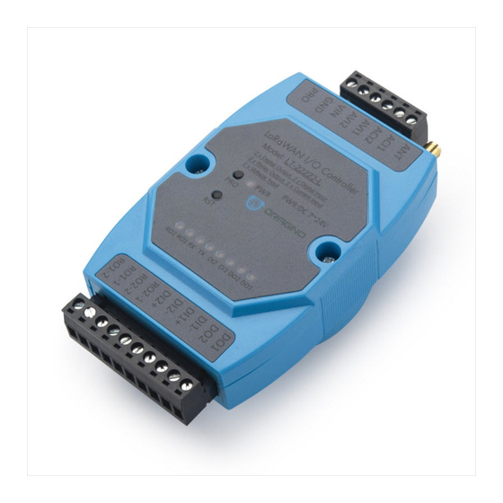
LT Series LoRa IO Controller User Manual
Document Version: 1.5.7
Image Version: v1.5.4
Version
Description
1.0
Release
1.0.2
Add 8 ch
1.0.3
Add current measure photo
1.0.4
Add Cayenne connection guide
1.1
Add downlink trouble shooting, Add Hardware Source code link.
Add change log for v1.1. (related to Downlink, Payload part)
Add TTN payload format
1.1.1
Add more info for 8 channel mode descript and troubleshooting while use
US915 and AU915
1.1.2
Modify trouble shooting for upload via FlashLoader,
LT Series LoRa IO controller User Manual
annels mode for US915, AU915, CN470
www.dragino.com
Date
2018-Sep-26
2018-Oct-24
2018-Nov-2
2018-Nov-24
2019-Jan-24
2019-Feb-21
2019-Apr-26
1 / 50
Advertisement
Table of Contents

Related Manuals for Dragino LT Series


Summary of Contents for Dragino LT Series
- Page 1 LT Series LoRa IO Controller User Manual Document Version: 1.5.7 Image Version: v1.5.4 Version Description Date Release 2018-Sep-26 annels mode for US915, AU915, CN470 1.0.2 Add 8 ch 2018-Oct-24 1.0.3 Add current measure photo 2018-Nov-2 1.0.4 Add Cayenne connection guide 2018-Nov-24 Add downlink trouble shooting, Add Hardware Source code link.
- Page 2 Modify content to support v1.5.4 firmware 2020-Dec-30 1.5.5 Fix typo for upgrade LED status 2021-Jan-13 1.5.6 Add FAQ for counting 2022-Jan-25 1.5.7 Add wiring example for analog input to 4~20mA sensor 2022-Feb-26 LT Series LoRa IO controller User Manual 2 / 50...
-
Page 3: Table Of Contents
Introduction ..........................6 What is LT Series I/O Controller ....................6 Specifications ..........................7 Features ............................8 Applications ..........................8 Hardware Variants ........................9 Firmware Change log ......................... 9 Power ON Device ........................10 Operation Mode ........................11 How it works? ........................... 11 Example to join LoRaWAN network .................. - Page 4 Have trouble to upload image....................48 Why I can’t join TTN in US915 /AU915 bands? ................. 48 Order Info ..........................48 Packing Info ..........................48 Support ........................... 49 Reference ........................... 50 LT Series LoRa IO controller User Manual 4 / 50...
- Page 5 LT Series LoRa IO controller User Manual 5 / 50...
-
Page 6: Introduction
1. Introduction 1.1 What is LT Series I/O Controller The Dragino LT series I/O Modules are Long Range LoRaWAN I/O Controller. It contains different I/O Interfaces such as: analog current Input, analog voltage input, relay output, digital input and digital output etc. The LT I/O Modules are designed to simplify the installation of I/O monitoring. -
Page 7: Specifications
Low RX current of 10.3 mA, 200 nA register retention. ➢ Fully integrated synthesizer with a resolution of 61 Hz. ➢ FSK, GFSK, MSK, GMSK, LoRaTM and OOK modulation. ➢ Built-in bit synchronizer for clock recovery. ➢ Preamble detection. LT Series LoRa IO controller User Manual 7 / 50... -
Page 8: Features
Firmware upgradable via program port ✓ Counting 1.4 Applications ✓ Smart Buildings & Home Automation ✓ Logistics and Supply Chain Management ✓ Smart Metering ✓ Smart Agriculture ✓ Smart Cities ✓ Smart Factory LT Series LoRa IO controller User Manual 8 / 50... -
Page 9: Hardware Variants
2 x 0~20mA Analog Input (res:0.01mA) ✓ 2 x 0~30V Analog Input (res:0.01v) ✓ 1 x Counting Port 1.6 Firmware Change log LT Image files: http://www.dragino.com/downloads/index.php?dir=LT_LoRa_IO_Controller/LT33222-L/image/ Change log: http://www.dragino.com/downloads/index.php?dir=LT_LoRa_IO_Controller/LT33222- L/image/&file=changelog LT Series LoRa IO controller User Manual 9 / 50... -
Page 10: Power On Device
The LT controller can be powered by 7 ~ 24V DC power source. Connect VIN to Power Input V+ and GND to power input V- to power the LT controller. PWR will on when device is properly powered. LT Series LoRa IO controller User Manual 10 / 50... -
Page 11: Operation Mode
TTN: Step 1: Create a device in TTN with the OTAA keys from LT IO controller. Each LT is shipped with a sticker with the default device EUI as below: LT Series LoRa IO controller User Manual 11 / 50... - Page 12 Step 2: Power on LT and it will auto join to the TTN network. After join success, it will start to upload message to TTN and user can see in the panel. LT Series LoRa IO controller User Manual 12 / 50...
-
Page 13: Uplink Payload
[0] DI2 channel is low input; ✓ [1] DI1 channel is high input and DI1 LED is OFF; LT22222-L: ✓ [1] DI2 channel is high input and DI2 LED is ON; LT Series LoRa IO controller User Manual 13 / 50... -
Page 14: At+Mod=2, (Double Di Counting)
AT+TRIG1=1,100 (set DI3 port to trigger on high level, valid signal is 100ms ) AT+SETCNT=1,60 (Set COUNT1 value to 60) For LT22222-L: AT+TRIG1=0,100 (set DI1 port to trigger on low level, valid signal is 100ms) LT Series LoRa IO controller User Manual 14 / 50... -
Page 15: At+Mod=3, Single Di Counting + 2 X Aci
DO is for reverse digital output. DOx=1: output low, DOx=0: high or float. Note: DO3 is not valid for LT-22222-L. To use counting mode, please run: AT+MOD=3 Other AT Commands for counting are similar to MOD2 Counting Command. LT Series LoRa IO controller User Manual 15 / 50... -
Page 16: At+Mod=4, Single Di Counting + 1 X Voltage Counting
3.3.5 AT+MOD=5, Single DI Counting + 2 x AVI + 1 x ACI LT33222-L: This mode the DI3 is used as a counting pin. LT22222-L: This mode the DI1 is used as a counting pin. LT Series LoRa IO controller User Manual 16 / 50... - Page 17 DO is for reverse digital output. DOx=1: output low, DOx=0: high or float. Note: DO3 is not valid for LT-22222-L. To use this mode, please run: AT+MOD=5 Other AT Commands for counting are similar to MOD2 Counting Command. LT Series LoRa IO controller User Manual 17 / 50...
-
Page 18: At+Addmod=6. (Trigger Mode, Optional)
(If ACI1 voltage lower than 10mA or higher than 15mA, trigger an uplink) Trigger base on DI status: DI status trigger Flag. Format: AT+DTRI=<DI1_TIRGGER_FlAG>,< DI2_TIRGGER_FlAG > Example: AT+ DTRI =1,0 (Enable DI1 trigger / disable DI2 trigger) LT Series LoRa IO controller User Manual 18 / 50... - Page 19 AC2_ HIGH HIGH HIGH HIGH ✓ Each bits shows which status has been trigger on this uplink. Example: 10000000: Means this packet is trigger by AC1_LOW. Means voltage too low. LT Series LoRa IO controller User Manual 19 / 50...
-
Page 20: Payload Decoder
: 0x01: MOD6 is enable. 0x00: MOD6 is disable. Downlink command to poll MOD6 status: AB 06 When device got this command, it will send the MOD6 payload. 3.3.7 Payload Decoder Decoder for TTN/loraserver/ChirpStack http://www.dragino.com/downloads/index.php?dir=LT_LoRa_IO_Controller/LT33222-L/Payload_decoder/ LT Series LoRa IO controller User Manual 20 / 50...
Need help?
Do you have a question about the LT Series and is the answer not in the manual?
Questions and answers