Table of Contents
Advertisement
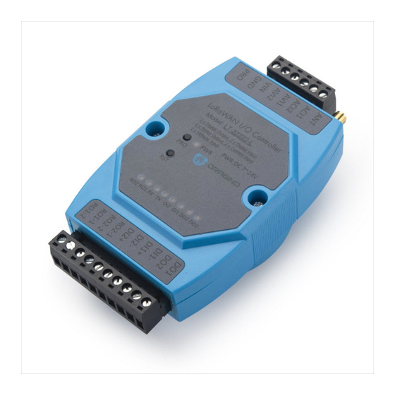
LT Series LoRa IO Controller User Manual
Document Version: 1.4.2
Image Version: v1.4
Version
Description
1.0
Release
annels mode for US915, AU915, CN470
1.0.2
Add 8 ch
1.0.3
Add current measure photo
1.0.4
Add Cayenne connection guide
1.1
Add downlink trouble shooting, Add Hardware Source code link.
Add change log for v1.1. (related to Downlink, Payload part)
Add TTN payload format
1.1.1
Add more info for 8 channel mode descript and troubleshooting while use
US915 and AU915
1.1.2
Modify trouble shooting for upload via FlashLoader,
LT Series LoRa IO controller User Manual
www.dragino.com
Date
2018-Sep-26
2018-Oct-24
2018-Nov-2
2018-Nov-24
2019-Jan-24
2019-Feb-21
2019-Apr-26
1 / 42
Advertisement
Table of Contents

Subscribe to Our Youtube Channel
Related Manuals for Dragino LT Series


Summary of Contents for Dragino LT Series
- Page 1 LT Series LoRa IO Controller User Manual Document Version: 1.4.2 Image Version: v1.4 Version Description Date Release 2018-Sep-26 annels mode for US915, AU915, CN470 1.0.2 2018-Oct-24 Add 8 ch 1.0.3 Add current measure photo 2018-Nov-2 1.0.4 Add Cayenne connection guide 2018-Nov-24 Add downlink trouble shooting, Add Hardware Source code link.
- Page 2 2019-Aug-20 1.4.0 Add LT-22222-L description and support. 2020-Mar-7 Add Decode in LoRaserver 1.4.1 Modify Downlink trouble shooting, Add MyDevice Photo 2020-Mar-28 1.4.2 Add Upgrade info for v1.4.2 firmware version 2020-Mar-30 LT Series LoRa IO controller User Manual 2 / 42...
-
Page 3: Table Of Contents
Introduction ..........................5 What is LT Series I/O Controller ....................5 Specifications ..........................6 Features ............................7 Applications ..........................7 Hardware Variants ........................8 Firmware Change log ......................... 8 Power ON Device ........................10 Operation Mode ........................11 How it works? ........................... 11 Example to join LoRaWAN network .................. - Page 4 Have trouble to upload image....................40 Why I can’t join TTN in US915 /AU915 bands? ................. 40 Order Info ..........................40 Packing Info ..........................40 Support ........................... 41 Reference ..........................42 LT Series LoRa IO controller User Manual 4 / 42...
-
Page 5: Introduction
1. Introduction 1.1 What is LT Series I/O Controller The Dragino LT series I/O Modules are Long Range LoRaWAN I/O Controller. It contains different I/O Interfaces such as: analog current Input, analog voltage input, relay output, digital input and digital output etc. The LT I/O Modules are designed to simplify the installation of I/O monitoring. -
Page 6: Specifications
Low RX current of 10.3 mA, 200 nA register retention. Fully integrated synthesizer with a resolution of 61 Hz. FSK, GFSK, MSK, GMSK, LoRaTM and OOK modulation. Built-in bit synchronizer for clock recovery. Preamble detection. LT Series LoRa IO controller User Manual 6 / 42... -
Page 7: Features
Firmware upgradable via program port Counting 1.4 Applications Smart Buildings & Home Automation Logistics and Supply Chain Management Smart Metering Smart Agriculture Smart Cities Smart Factory LT Series LoRa IO controller User Manual 7 / 42... -
Page 8: Hardware Variants
Add Software Watchdog Re-construct Payload format, use the new decoder for v1.4. Add Downlink command to pre-set count number First bug for endless loop when TDC is too small LT Series LoRa IO controller User Manual 8 / 42... - Page 9 Voltage and Current reserve three decimal, previous is two Can use any Fport for downlink Add AT+CFG to print all settings Fix current and voltage glith bug LT Series LoRa IO controller User Manual 9 / 42...
-
Page 10: Power On Device
The LT controller can be powered by 7 ~ 24V DC power source. Connect VIN to Power Input V+ and GND to power input V- to power the LT controller. PWR will on when device is properly powered. LT Series LoRa IO controller User Manual 10 / 42... -
Page 11: Operation Mode
TTN: Step 1: Create a device in TTN with the OTAA keys from LT IO controller. Each LT is shipped with a sticker with the default device EUI as below: LT Series LoRa IO controller User Manual 11 / 42... - Page 12 Step 2: Power on LT and it will auto join to the TTN network. After join success, it will start to upload message to TTN and user can see in the panel. LT Series LoRa IO controller User Manual 12 / 42...
-
Page 13: Uplink Payload
[1] DI1 channel is high input and DI1 LED is OFF; LT22222-L: [1] DI2 channel is high input and DI2 LED is ON; [0] DI1 channel is low input; LT Series LoRa IO controller User Manual 13 / 42... -
Page 14: At+Mod=2, (Double Di Counting)
For LT22222-L: AT+TRIG=0,100, 1 (set DI1 port to trigger on low level, valid signal is 100ms) AT+TRIG=1,100, 1 (set DI1 port to trigger on high level, valid signal is 100ms ) LT Series LoRa IO controller User Manual 14 / 42... -
Page 15: At+Mod=3, Single Di Counting + 2 X Aci
DO is for reverse digital output. DOx=1: output low, DOx=0: high or float. Note: DO3 is not valid for LT-22222-L. To use counting mode, please run: AT+MOD=3 Other AT Commands for counting are similar to MOD2 Counting Command. LT Series LoRa IO controller User Manual 15 / 42... -
Page 16: At+Mod=4, Single Di Counting + 1 X Voltage Counting
This mode the DI3 is used as a counting pin. LT22222-L: This mode the DI1 is used as a counting pin. Size(bytes) 2 Value AVI1 AVI2 ACI1 COUNT1 DIDORO* Reserve voltage voltage Current LT Series LoRa IO controller User Manual 16 / 42... -
Page 17: Payload Decoder
Note: DO3 is not valid for LT-22222-L. To use this mode, please run: AT+MOD=5 Other AT Commands for counting are similar to MOD2 Counting Command. 3.3.6 Payload Decoder Decoder for TTN/loraserver/ChirpStack http://www.dragino.com/downloads/index.php?dir=LT_LoRa_IO_Controller/LT33222-L/Payload_decoder/ LT Series LoRa IO controller User Manual 17 / 42... -
Page 18: Downlink Payload
02 11 01 00 No Action High Note: For LT-22222-L, there is no DO3, the last byte can use any value. Device will upload a packet if downlink code execute successfully. LT Series LoRa IO controller User Manual 18 / 42... - Page 19 RO1 to NO, RO2 No Action Fourth / Fifth Bytes: Latching time. Unit: ms Device will upload a packet if downlink code execute successfully. Example payload: a) 05 01 11 07 D0 LT Series LoRa IO controller User Manual 19 / 42...
- Page 20 01: Set COUNT1 count value 02: Set COUNT2 count value 03: Set AV1 count number. bytes: the new value in hex format: 00 00 00 AB: count: 0xAB = 171. Digital Output CTL (DO1DO2DO3) LT Series LoRa IO controller User Manual 20 / 42...
- Page 21 A9 00 00 00 00 07 D0 DO1 pin & DO2 pin & DO3 pin will be set to high , last 2 seconds, then both change to low. LT Series LoRa IO controller User Manual 21 / 42...
-
Page 22: Integrate With Mydevice
Step 1: Be sure that your device is programmed and properly connected to the network at this time. Step 2: To configure the Application to forward data to Mydevices you will need to add integration. To add the Mydevices integration, perform the following steps: LT Series LoRa IO controller User Manual 22 / 42... - Page 23 Step 4: Search LT-22222-L(for both LT-22222-L / LT-33222-L) and add DevEUI. Search under The things network After added, the sensor data arrive TTN, it will also arrive and show in Mydevices. LT Series LoRa IO controller User Manual 23 / 42...
- Page 24 LT Series LoRa IO controller User Manual 24 / 42...
-
Page 25: Interface Detail
3.6 Interface Detail 3.6.1 Digital Input Port: DI1/DI2 /DI3 ( For LT-33222-L, low active ) Support NPN Type sensor LT Series LoRa IO controller User Manual 25 / 42... -
Page 26: Digital Input Port: Di1/Di2 ( For Lt-22222-L)
�� = DI1+ / 51K. �� If sensor output is 220v, the �� = 4.3mA , So the LT-22222-L will be able to detect this high active �� signal safely. LT Series LoRa IO controller User Manual 26 / 42... -
Page 27: Digital Output Port: Do1/Do2 /Do3
The LT serial controller has two relay interfaces; each interface uses two pins of the screw terminal. User can connect other device’s Power Line to in serial of RO1_1 and RO_2. Such as below: LT Series LoRa IO controller User Manual 27 / 42... - Page 28 LT Series LoRa IO controller User Manual 28 / 42...
-
Page 29: Leds Indicators
For LT-33222-L ONLY: ON when DI3 is low, LOW when DI3 is high For LT-22222-L: ON when DI2 is high, LOW when DI2 is low For LT-33222-L: ON when DI2 is low, LOW when DI2 is high LT Series LoRa IO controller User Manual 29 / 42... -
Page 30: Use At Command
AT+FDR: Reset Parameters to Factory Default, Keys Reserve AT+DEUI: Get or Set the Device EUI AT+DADDR: Get or Set the Device Address AT+APPKEY: Get or Set the Application Key AT+NWKSKEY: Get or Set the Network Session Key LT Series LoRa IO controller User Manual 30 / 42... - Page 31 AT+PWORD: Set password, max 9 digits AT+CHS: Get or Set Frequency (Unit: Hz) for Single Channel Mode AT+CHE: Get or Set eight channels mode, Only for US915, AU915, CN470 AT+CFG: Print all settings LT Series LoRa IO controller User Manual 31 / 42...
-
Page 32: Common At Command Sequence
4. The command AT+RX2FQ and AT+RX2DR is to let downlink work. to set the correct parameters, user can check the actually downlink parameters to be used. As below. Which shows the RX2FQ should use 868400000 and RX2DR should be 5 LT Series LoRa IO controller User Manual 32 / 42... -
Page 33: Change To Class A
4.2.3 Change to Class A If sensor JOINED AT+CLASS=A LT Series LoRa IO controller User Manual 33 / 42... -
Page 34: Faq
Hold down the PRO button and then momentarily press the RST reset button and the DO2 led will change from OFF to ON. When DO2 LED is on, it means the device is in download mode. LT Series LoRa IO controller User Manual 34 / 42... - Page 35 Board detected LT Series LoRa IO controller User Manual 35 / 42...
-
Page 36: How To Change The Lora Frequency Bands/Region
For example, in US915 band, the frequency table is as below. By default, end node will use all channels (0~71) for OTAA Join process. After OTAA JOINED, end node will use these all channels (0~71) to send uplink packets. LT Series LoRa IO controller User Manual 36 / 42... - Page 37 919.2 919.4 919.6 919.8 Channel 16-23 920.2 920.4 920.6 920.8 921.2 921.4 Channel 24-31 921.6 921.8 922.2 922.4 922.6 922.8 Channel 32-39 923.2 923.4 923.6 923.8 924.2 924.4 924.6 Channel 40-47 LT Series LoRa IO controller User Manual 37 / 42...
-
Page 38: How To Set Up Lt To Work With Single Channel Gateway Such As Lg01/Lg02
AT+NJM=0 Set to ABP mode AT+ADR=0 Set the Adaptive Data Rate Off AT+DR=5 Set Data Rate (Set AT+DR=3 for 915 band) AT+TDC=60000 Set transmit interval to 60 seconds AT+CHS=868400000 Set transmit frequency to 868.4Mhz LT Series LoRa IO controller User Manual 38 / 42... - Page 39 AT+DADDR=26 01 1A F1 Set Device Address to 26 01 1A F1 Reset MCU As shown in below: LT Series LoRa IO controller User Manual 39 / 42...
-
Page 40: Trouble Shooting
Program cable x 1 Dimension and weight: Device Size: 13.5 x 7 x 3 cm Device Weight: 105g Package Size / pcs : 14.5 x 8 x 5 cm LT Series LoRa IO controller User Manual 40 / 42... -
Page 41: Support
Provide as much information as possible regarding your enquiry (product models, accurately describe your problem and steps to replicate it etc) and send a mail to support@dragino.com LT Series LoRa IO controller User Manual 41 / 42... -
Page 42: Reference
10. Reference Product Page: LT-33222-L: http://www.dragino.com/products/lora-lorawan-end-node/item/138-lt-33222-l.html LT-22222-L: http://www.dragino.com/products/lora-lorawan-end-node/item/156-lt-22222-l.html Image Download AT Command Manual Hardware Source LT Series LoRa IO controller User Manual 42 / 42...
Need help?
Do you have a question about the LT Series and is the answer not in the manual?
Questions and answers