
Subscribe to Our Youtube Channel
Related Manuals for Dragino LT Series


Summary of Contents for Dragino LT Series
- Page 1 LT Series LoRa IO Controller User Manual Document Version: 1.3 Firmware Version: V1.2 1 / 37 LT Series IO Controller User Manual – Ver 1.3...
- Page 2 Adjust Downlink instruction while using with LG01-N and LG02 2019-5-7 1.2.2 Add new feature on downlink, able to control the relay base on timing. Various minor text and format edits. 2019-6-4 2 / 37 LT Series IO Controller User Manual – Ver 1.3...
-
Page 3: Table Of Contents
4.1 Why there are 433/868/915 versions?............27 4.2 What is the frequency range of LT LoRa device?.........27 4.3 How to upgrade the firmware image?............28 4.4 How to change the LoRa Frequency Bands/Region........30 3 / 37 LT Series IO Controller User Manual – Ver 1.3... - Page 4 5.2 Connection problem while using USB <----> TTL to upload firmware..35 5.3 Why I can’t join TTN in US915 /AU915 bands?..........36 6 Order Info..................36 7 Packing Info..................36 8 Support..................37 9 Reference..................37 4 / 37 LT Series IO Controller User Manual – Ver 1.3...
-
Page 5: Introduction
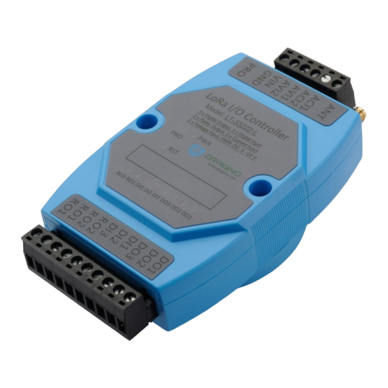
Introduction 1.1 What is LT Series I/O Controller The Dragino LT series I/O Modules are long range LoRaWAN I/O Controllers. The controllers contain various I/O Interfaces including: analog current input, analog voltage input, relay output, digital input and digital output. The LT I/O Modules are designed to simplify the installation of I/O monitoring facilities. -
Page 6: Specifications
Preamble detection. 127 dB Dynamic Range RSSI. Automatic RF Sense and CAD with ultra-fast AFC. Packet engine up to 256 bytes with CRC. 6 / 37 LT Series IO Controller User Manual – Ver 1.3... -
Page 7: Features
Voltage and Current reserve three decimal, previously two Allow use of any Fport for downlink Add AT+CFG to print all settings Fix current and voltage glith bug 7 / 37 LT Series IO Controller User Manual – Ver 1.3... -
Page 8: Operation Mode
LoRaWAN gateway. The LG308 is set up by default to connect to the TTN network, so it is simply necessary to configure TTN Server to recognise the device. 8 / 37 LT Series IO Controller User Manual – Ver 1.3... - Page 9 Each LT is shipped with a sticker with the default device EUI as shown below: You can enter these keys in the LoRaWAN Server portal as shown below.. Add APP EUI in the application. Add APP KEY and DEV EUI 9 / 37 LT Series IO Controller User Manual – Ver 1.3...
-
Page 10: Uplink Payload (At+Mod=1, General Mode)
ROx=1 : Close ROx=0 : Open. DI is for digital input. DIx=1: high or float, DIx=0: low. DO is for digital output. DOx=1: output low, DOx=0: high or float. 10 / 37 LT Series IO Controller User Manual – Ver 1.3... - Page 11 DO1 is float if there is no load between DO1 and V+.; • DO1 is high if there is a load between DO1 and V+. • DO1 LED is off in both case • 11 / 37 LT Series IO Controller User Manual – Ver 1.3...
- Page 12 DI1=(value&0x08)? “H":"L"; //DI1 Digital Input Status var DI2=(value&0x10)? "H":"L"; //DI2 Digital Input Status var DI3=(value&0x20)? "H":"L"; //DI3 Digital Input Status var RO2=(value&0x40)? "ON":"OFF"; //RO2 Relay Status var RO1=(value&0x80)? "ON":"OFF"; //RO1 Relay Status 12 / 37 LT Series IO Controller User Manual – Ver 1.3...
- Page 13 { ACI1_mA:ACI1, ACI2_mA:ACI2, AVI1_V:AVI1, AVI2_V:AVI2, DO1_status:DO1, DO2_status:DO2, DO3_status:DO3, DI1_status:DI1, DI2_status:DI2, DI3_status:DI3, RO1_status:RO1, RO2_status:RO2, 13 / 37 LT Series IO Controller User Manual – Ver 1.3...
-
Page 14: Uplink Payload (At+Mod=2, Counting Mode)
= 0, this value is 1, means this packet is the first packet after JOIN the network. Note: this 16 byte payload will be blank for the 915Mhz DR0 mode which only supports a one byte payload. 14 / 37 LT Series IO Controller User Manual – Ver 1.3... - Page 15 First=(value&0x20)? "Yes":"No"; //First First payload for join network var RO2=(value&0x40)? "ON":"OFF"; //RO2 Relay Status var RO1=(value&0x80)? "ON":"OFF"; //RO1 Relay Status return { BatV:batV, Count1_times:count1, Count2_times:count2, Count3_times:count3, DO1_status:DO1, DO2_status:DO2, DO3_status:DO3, First_status:First, RO1_status:RO1, RO2_status:RO2, 15 / 37 LT Series IO Controller User Manual – Ver 1.3...
-
Page 16: Downlink Payload
Type code 02 means Digital Output. If payload = 0x030100, it means set RO1 to Close and RO2 to Open. If payload = 0x04FF, it will reset the LT. 16 / 37 LT Series IO Controller User Manual – Ver 1.3... - Page 17 Relay1 will change to NC, Relay2 will change to NO. d) 05 00 00 07 D0 Relay1 and Relay2 will change to NC, last 2 seconds, then both change to NO. 17 / 37 LT Series IO Controller User Manual – Ver 1.3...
-
Page 18: Show Data On Cayenne
Step 2: To configure your Application to forward data to Cayenne you will need to add an Integration. To add the Cayenne integration, perform the following steps: 18 / 37 LT Series IO Controller User Manual – Ver 1.3... - Page 19 Step 3: Create an account or log in in the mydevices cayenne. Step 4: Search the LT-33222and add DevEUI 19 / 37 LT Series IO Controller User Manual – Ver 1.3...
- Page 20 20 / 37 LT Series IO Controller User Manual – Ver 1.3...
-
Page 21: Interface Detail
The analog input interface is as shown below. The LT will measure the IN2 voltage so to calculate the current passing through the Load. The formula is: AC2 = (IN2 voltage ) / 12 21 / 37 LT Series IO Controller User Manual – Ver 1.3... -
Page 22: Use At Command
LT. The AT Command facility is disabled by default, and you need to enter the password (default:123456) to enable the AT Commands facility as shown below. 22 / 37 LT Series IO Controller User Manual – Ver 1.3... - Page 23 AT+CLASS : Get or Set the Device Class AT+JOIN : Join network AT+NJS : Get OTAA Join Status AT+SENDB : Send hexadecimal data along with the application port 23 / 37 LT Series IO Controller User Manual – Ver 1.3...
- Page 24 : Get or Set Frequency (Unit: Hz) for Single Channel Mode AT+CHE : Get or Set 8 channels mode. Only for US915, AU915, CN470 AT+CFG : Print all settings 24 / 37 LT Series IO Controller User Manual – Ver 1.3...
-
Page 25: Common At Command Sequences
AT+RX2DR=5 Set RX2DR to match the downlink DR from server. see below AT+DADDR=26 01 1A F1 Set Device Address to 26 01 1A F1, this ID can be found in the LoRa Server portal. Reset MCU 25 / 37 LT Series IO Controller User Manual – Ver 1.3... -
Page 26: Change To Class C
RX2FQ should be 868400000 and RX2DR should be 5. 3.2.3 Change to Class C From ABP, CLASS A to OTAA, CLASS C AT+NJM=1 AT+CLASS=C From OTAA, CLASS A to OTAA, CLASS C If sensor JOINED AT+CLASS=C 26 / 37 LT Series IO Controller User Manual – Ver 1.3... -
Page 27: Faq
Working Frequency Best Tune Recommend Frequency Bands SX1278 Band2(LF): 410 ~525 Mhz 433Mhz CN470/EU433 SX1276 Band1(HF): 862~1020 Mhz 868Mhz EU868 SX1276 Band1(HF): 862 ~1020 Mhz 915Mhz AS923/AU915/ KR920/US915 27 / 37 LT Series IO Controller User Manual – Ver 1.3... -
Page 28: How To Upgrade The Firmware Image
Hold down the PRO button and then momentarily press the RST reset button and the DO2 led will change from OFF to ON The following screen shots show the process. 28 / 37 LT Series IO Controller User Manual – Ver 1.3... - Page 29 Board detected 29 / 37 LT Series IO Controller User Manual – Ver 1.3...
-
Page 30: How To Change The Lora Frequency Bands/Region
72 frequencies. You can configure the end node to work in 8 channel mode by using the AT+CHE command. The 500kHz channels are always included for OTAA. 30 / 37 LT Series IO Controller User Manual – Ver 1.3... - Page 31 8 channel mode. The device will then work in Channel 8-15 & 64-71 for OTAA, and channel 8-15 for Uplink. 31 / 37 LT Series IO Controller User Manual – Ver 1.3...
- Page 32 924.8 925.2 925.4 925.6 925.8 926.2 Channel 48-55 926.4 926.6 926.8 927.2 927.4 927.6 927.8 Channel 56-63 Channels(500KHz,4/5,Unit:MHz,CHS=0) 915.9 917.5 919.1 920.7 922.3 923.9 925.5 927.1 Channel 64-71 32 / 37 LT Series IO Controller User Manual – Ver 1.3...
-
Page 33: How To Set Up Lt To Work With Single Channel Gateway Such As Lg01/Lg02
AT+DR=5 Set Data Rate (Set AT+DR=3 for 915 band) AT+TDC=60000 Set transmit interval to 60 seconds AT+CHS=868400000 Set transmit frequency to 868.4Mhz AT+DADDR=26 01 1A F1 Set Device Address to 26 01 1A F1 Reset MCU 33 / 37 LT Series IO Controller User Manual – Ver 1.3... - Page 34 As shown in below: 34 / 37 LT Series IO Controller User Manual – Ver 1.3...
-
Page 35: Trouble Shooting
ISP/Flash Switch in different position. c) check if reset button works. 3. If you use Windows10 system. Please change the flash loader to run in Windows7 compatibility mode. 35 / 37 LT Series IO Controller User Manual – Ver 1.3... -
Page 36: Why I Can't Join Ttn In Us915 /Au915 Bands
Device Size: 13.5 x 7 x 3 cm Device Weight: 105g Package Size / pcs : 14.5 x 8 x 5 cm Weight / pcs : 170g 36 / 37 LT Series IO Controller User Manual – Ver 1.3... -
Page 37: Support
Reference Product Page Image Download AT Command Manual Hardware Source 37 / 37 LT Series IO Controller User Manual – Ver 1.3...
Need help?
Do you have a question about the LT Series and is the answer not in the manual?
Questions and answers