Table of Contents
Advertisement
Incorporated in this document are the following:
• Declaration of conformity
• Technical manual
• Dimensional drawing
Multiple instructions:
MTEC.3630.GB-A-1 Operation and maintenance manual LSA series English Rev. A 07-2018
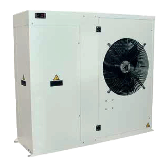
HIGH EFFICIENCY AIR TO WATER HEAT PUMPS
LSA/HP
TECHNICAL MANUAL
SERIES
Read and understand
the instructions before
undertaking any work on
the unit
Original instructions
Advertisement
Table of Contents

Related Manuals for HIdRos LSA/HP Series


Summary of Contents for HIdRos LSA/HP Series
- Page 1 HIGH EFFICIENCY AIR TO WATER HEAT PUMPS LSA/HP SERIES TECHNICAL MANUAL Incorporated in this document are the following: • Declaration of conformity • Technical manual • Dimensional drawing Read and understand Multiple instructions: the instructions before undertaking any work on the unit MTEC.3630.GB-A-1 Operation and maintenance manual LSA series English Rev.
- Page 2 LSA/HP Reproduction, data storage and transmission, even partial, of this publication, in any form, without the prior written authorisation of the Company, is prohibited. The Company can be contacted for all inquiries regarding the use of its products. equipment and instructions regarding use and maintenance at any time, without notice. Declaration of conformity We declare under our own responsibility that the below equipment complies in all parts with the CEE and EN directives.
-
Page 3: Table Of Contents
LSA/HP INDEX 1. INTRODUCTION ..................................... 1.1 Preliminary information ..............................1.2 Aim and content of the manual ............................1.3 How to store this manual ..............................1.4 Manual updates ................................. 1.5 How to use this manual ..............................1.6 Potential risks ..................................1.7 General description of symbols used ..........................1.8 Safety symbols used ................................ - Page 4 LSA/HP 6.2 Stop ....................................6.3 Stand-by .................................... 6.4 How to change the set points ............................6.5 Parameters list ................................... 6.6 Acoustic signal silencing ..............................6.7 Alarm reset ..................................6.8 Display alarm history ................................. 7. MAINTENANCE OF THE UNIT ................................7.1 General warnings ................................7.2 Access to the unit ................................
-
Page 5: Introduction
LSA/HP 1. INTRODUCTION 1.1 Preliminary information Reproduction, storage or transmission of any part of this publication in any form, without the prior written consent of the Company, is pro- hibited. The unit to which these instructions refer, is designed to be used for the the purposes described and to be operated in accordance with these instructions. -
Page 6: Potential Risks
LSA/HP 1.6 Potential Risks Whilst the unit has been designed to minimize any risk posed to the safety of people who will interact with it, it has not been technically possible to eliminate completely the causes of risk. It is therefore necessary to refer to the requirements and symbolism below: LOCATION OF POTENTIAL RISK METHOD OF INJURY... -
Page 7: General Description Of Symbols Used
LSA/HP 1.7 General Description of Symbols Used Safety symbols combined in accordance with ISO 3864-2: BANNED A black symbol inside a red circle with a red diagonal indicates an action that should not be performed. WARNING A black graphic symbol added to a yellow triangle with black edges indicates danger. ACTION REQUIRED A white symbol inserted in a blue circle indicates an action that must be done to avoid a risk. -
Page 8: Safety Symbols Used
LSA/HP 1.8 Safety symbols used GENERAL RISK Observe all signs placed next to the pictogram. The failure to follow directions may create a risk situation that may be injurious to the user. ELECTRICAL HAZARD Observe all signs placed next to the pictogram. The symbol indicates components of the unit and actions described in this manual that could create an electrical hazard. - Page 9 For all electrical information not provided on the label, refer to the wiring diagram. A facsimile of the label is shown below: Manufacturer: PD322111 Via E. Mattei, 20 35028 Piove di Sacco PD - Italy +39 049 9731022 info@hidros.it www.hidros.eu 123456 1LSA.014A-1A Modello Matricola...
-
Page 10: Safety
LSA/HP 2. SAFETY 2.1 Warning re potentially hazardous toxic substances The lubricant used is polyester oil. Please refer to the information provided on the compressor data plate. For further information regarding the characteristics of the refrigerant and oil used, refer to the safety data sheets available from the refrigerant and oil manufacturers. -
Page 11: Prevention Of Inhalation Of High Vapor Concentrations
LSA/HP 2.4 Procedures to be adopted in the event of accidental release of refrigerant Ensure suitable personal protection (especially respiratory protection) during cleaning operations. If deemed safe, isolate the source of the leak. If the leakage is small and if adequate ventilation is provided, allow the refrigerant to evapo- rate. -
Page 12: Technical Characteristics
LSA/HP 3. TECHNICAL CHARACTERISTICS 3.1 Unit description The units has been designed for small and medium residential and commercial applications. They are suitable for generating chilled water at 7°C, commonly used in applications with fan coils and/or air handling units. solution to be selected. -
Page 13: Other Versions
LSA/HP discuss and evaluate, in conjunction with the customer, solutions using MODBUS protocols. The autoadaptive control system ACTIVE is an advanced strategy that continuously monitors the temperature of the inlet and outlet water thereby determining the variation of the building thermal load. -
Page 14: Accessories Description
LSA/HP 3.3 Accessories description 3.3.1 Low noise version (LS00) This version includes the complete acoustic insulation of the unit (compressor + heat exchangers vanes) with compressor jackets and insulating material made with high density media and the interposition of heavy bitumen layer. 3.3.2 Rubber vibration dampers (KAVG) To be installed beneath the unit base and the ground to avoid the transmission of vibrations (and the noise) to the building. - Page 15 LSA/HP 3.3.14 Accessories availability LSA/HP Main switch – – – – Flow switch – Microprocessor control – General alarm digital output – Remote on/off digital input – Liquid line solenoid valve VSLI LS low noise version LS00 Low ambient condensing pressure control DCCF Partial heat recovery RP00...
-
Page 16: Technical Data
LSA/HP 3.4 Technical data LSA/HP Cooling capacity (EN14511) 14,0 15,5 20,5 26,6 30,0 33,0 39,0 Total input power (EN14511) 10,5 11,8 13,8 EER (EN14511) Heating capacity (EN14511) 14,9 17,2 22,0 29,5 33,5 36,5 44,4 Total input power (EN14511) 10,7 COP (EN14511) Energy Class SCOP kWh/kWh... - Page 17 LSA/HP 3.4.1 LSA - Cooling capacity and compressors input power External temp. 43°C 40°C 35°C 30°C 25°C 20°C User water out temperature (°C) 20°C 25°C 30°C 35°C 40°C External temp. 43°C User water out temperature (°C) The cooling capacity of the compressor is obtained by multiplying the nominal values (PF PA), with water produced at 7 ° C, shown at page 16 and 17, for respective correction factors.
- Page 18 LSA/HP 3.4.2 LSA/HP - Heating capacity and compressors input power Water temperature Produced 50°C 45°C 35°C Ambient temperature (dry bulb) (°C) Water temperature Produced 35°C 45°C 50°C Ambient temperature (dry bulb) (°C) The capacity of the compressor is obtained by multiplying the nominal values (PF PA), with water produced at 7 ° C, shown at page 16 and 17, for respective correction factors.
- Page 19 LSA/HP 3.4.3 User heat exchanger water pressure drops 08÷10 21÷26 31÷36 MTEC.3630.GB-A-1 Operation and maintenance manual LSA series English Rev. A 07-2018...
- Page 20 LSA/HP 3.4.4 LSA/A1 Water pump available static pressure 80,0 08÷10 70,0 60,0 50,0 40,0 30,0 20,0 10,0 0,25 0,75 1,25 1,75 2,25 2,75 210,0 190,0 21÷26 170,0 150,0 130,0 110,0 90,0 70,0 50,0 30,0 10,0 MTEC.3630.GB-A-1 Operation and maintenance manual LSA series English Rev.
-
Page 21: Operation Limits
LSA/HP 3.5 Operational limits Heating mode Cooling mode with Cooling mode cond. press. contr. Ambient temperature (°C) result in evaporating temperatures that are too low leading to the operation of safety devices that will prevent unit operation. 3.5.2 User water temperature (Winter mode) Once the system has reached set up, the temperature at the user exchanger cannot fall below 30 °... -
Page 22: Correction Tables
LSA/HP 3.6 Correction tables 3.6.1 Operation with glycol Glycol percentage Freezing point (°C) IPCF WFCF PDCF -3.2 0.985 1.02 1.08 -7.8 0.98 0.99 1.05 1.12 -14.1 0.97 0.98 1.09 1.22 -22.3 0.965 0.97 1.14 1.25 -33.8 0.955 0.965 1.33 factor. Water temperature diff.(°C) CCCP 0.99... -
Page 23: Sound Data
LSA/HP 3.7 Sound data LOW NOISE VERSION (LS) Octave bands (Hz) Modd. dB(A) dB(A) 81,1 72,3 66,2 64,7 63,6 58,2 54,8 45,7 81,9 81,1 72,3 66,2 64,7 63,6 58,2 54,8 45,7 81,9 81,1 72,3 66,2 64,7 63,6 58,2 54,8 45,7 81,9 82,1 73,3... -
Page 24: Workers' Health And Safety
LSA/HP 4.2. Health and safety Considerations The workplace must be kept clean, tidy and free from objects that may prevent free movement. Appropriate ligh- ting of the work place shall be provided to allow the operator to perform the required operations safely. Poor or too strong lighting can cause risks. -
Page 25: Storage
LSA/HP 4.5 Storage Units should be stored under cover and ideally, should remain in their packaging. The tools that are supplied for opening the electrics box should be formally transferred to the person responsible for the plant. 4.6 Unpacking Packaging could be dangerous for the operators. It is advisable to leave packaged units during handling and remove it before the installation. -
Page 26: Location And Minimum Technical Clearances
LSA/HP 4.8 Location and minimum technical clearances The unit has to be installed such that maintenance and repair is possible. The warranty does not cover costs for the provision of lifting apparatus, platforms or other lifting systems required to perform repairs during warranty period. The installation site should be chosen in accordance with EN 378-1 and 378-3 standards. -
Page 27: Installation Of Rubber Vibration Dampers (Kavg)
LSA/HP 4.9 Installation of rubber vibration dampers (KAVG) All units should be installed on vibration dampers in order to prevent the transmission of vibration to the supporting surface and reduce the noise level. Rubber vibration dampers are available as an option in the catalogue. The vibration dampers (optional) are supplied by the factory in seperate packaging. -
Page 28: Installation Of Condensate Drip Tray (Brca)
LSA/HP 4.11 Installation of condensate drip tray (BRCA) (Only for reversible units HP) In heating and domestic hot water mode, the unit can produce a quantity of condensate, depending upon the am- bient conditions and the working hours. The standard unit has a gap between the bottom of the coil and the base must therefore be installed in such a way as to prevent a slipping hazard to the user or third parties due to the presence of ice around the heat pump. -
Page 29: Chemical Characteristics Of The Water
LSA/HP It is compulsory to install on the USER WATER IN connection, a water strainer with a mesh not larger than 1 mm. and checked periodically. warranty will be invalidated. conditions: 7°C Dry bulb ambient temperature 35°C water outlet temperature 35°C dry bulb ambient temperature 7°C water outlet temperature 4.13 Chemical characteristics of the water... -
Page 30: Hydraulic Components
LSA/HP 4.16 Hydraulic components LSA/A1NT System Filling Group Water Pump Thermometer Flexible Connection Vent Valve Water Strainer Flow Switch Ball Shut-off Valve Drainage valve Water tank Expansion Vessel Temperature water sensor Safety Valve installer. If the unit is supplied without a pump, the pump must be installed with the supply side toward the water inlet con- nection of the unit. -
Page 31: Filling The Hydraulic Circuit
LSA/HP LSA/A1 System Filling Group Water Pump Thermometer Flexible Connection Vent Valve Water Strainer Flow Switch Ball Shut-off Valve Drainage valve Water tank Expansion Vessel Temperature water sensor Safety Valve installer. If the unit is supplied without a pump, the pump must be installed with the supply side toward the water inlet con- nection of the unit. -
Page 32: Wiring Connections: Preliminary Safety Information
LSA/HP The electric panel is located inside the unit at the top of the technical compartment where the various components of the refrigerant circuit are also to be found. To access the electrical board, remove the front panel of the unit: Power connections must be made in accordance to the wiring diagram enclosed with the unit and in accordance to the norms in force. -
Page 33: Electric Data
LSA/HP 4.20 Electric data The electrical data reported below refer to the standard unit without accessories. In all other cases refer to the data reported in the attached electrical wiring diagrams. please contact our Company. Model Power supply V/~/Hz 230/1/50 230/1/50 230/1/50 400/3+N50... -
Page 34: Electric Connections
LSA/HP 4.21 Electric connections The numbering of the terminals may change without notice. For their connection is mandatory to refer to the wiring diagram supplied along with the unit. 4.21.1 Remote wiring connections (opzional) All terminals referred to in the explanations below will be found on the terminal board inside the electrical box. All electric connections mentioned below have to be made by the installer, on site. -
Page 35: Refrigerant Circuit Layout
LSA/HP 4.22 Refrigerant circuit layout 4.22.1 Refrigerant circuit layout HP version Ø Ø Ø Ø Ø Ø Ø A1 NT Ø A1 ZZ A1NT One pump without water tank Centrifugal fan A1ZZ One pump with water tank Pump High pressure transducer Discharge valve User water input probe Exchangers heating... -
Page 36: Unit Start Up
LSA/HP 5. UNIT START UP 5.1 Preliminary checks Before starting the unit the checks detailed in this manual of the electric supply and connections, the hydraulic system and the refrigerant circuit, should be performed. Start-up operations must be performed in accordance with the instructions detailed in the previous paragraphs. If it is required to switch the unit on and off, never do this using the main isolator: this should only be used to discon- nect the unit from the power supply when the unit is to be permanently off. - Page 37 LSA/HP 5.1.2 Safety device setting Device Set-point Differential Reset Control thermostat (Heating mode) °C ----- Control thermostat (Cooling mode) °C ----- Anti-freeze thermostat MANUAL °C High pressure switch (standard version) Automatic for High pressure switch (CN version) 3 times (than 40.7 manual) Low pressure switch...
-
Page 38: Description Of The Control Panel
LSA/HP 5.2 Description of the control panel 5.2.1 Icone del display The instrument display is divided into three zones: Left zone: the display shows the icons. Top right zone: the display shows the inlet water temperature. Bottom right zone: The display shows the temperature of water utilities in output or, in the version with condensation control, the pressure of evaporation / condensation. -
Page 39: Remote Control Panel
LSA/HP 5.3 Remote control panel 5.3.1 Display icons Icon Meaning Icon Meaning Celsius degrees Electric heaters activated User water pump Compressor 1 Compressor 2 External fan General Alarm 5.3.2 Key function M makes it possible to enter the functions menu mode. - Page 40 LSA/HP 5.3.3 Installation To obtain IP65 protection for the panel, use the rubber gasket RGW-V (optional). For wall mounting use the V-KIT plastic adapter as illu- strated in the picture. Electric data can be updated without notice. It is therefore necessary to always refer to the wiring diagram provided in the unit.
-
Page 41: Use
LSA/HP 6. USE 6.1 Switch the unit on In order to power the unit, turn the main switch to the ON position. The display shows the User inlet water temperature. Legend Icon on if the open collector outlet is active. Function menu active. -
Page 42: Stop
LSA/HP 6.2 Stop 6.2.1 Cooling mode To stop the unit in cooling mode, press the key. The LED switches off. The unit goes into stand-by mode. 6.2.2 Heating mode To stop the unit in heating mode, press the key. The LED switches off. The unit goes into stand-by mode. 6.3 Stand-by When the unit is switched off from the keyboard or the remote panel, it goes into standby mode. -
Page 43: Parameters List
LSA/HP 6.4.1 Adjustable parameters Label Function Adjustment limit Default value SEt H Heating set-point 20÷55°C 40°C SEt C Cooling set-point 10÷23°C 12°C Password (Contact the company) The units are supplied with a very sophisticated control system with many other parameters that are not adjustable by the end user;... -
Page 44: Display Alarm History
LSA/HP 6.8 Display alarm history Press the key, then the keys, to scroll through the menus, when ALOG label appears in the bottom part of the display, press . To scroll the list of alarms use the keys. 7. MAINTENANCE OF THE UNIT 7.1 General warnings Starting from 01/01/2016 the new European Regulation 517_2014, “Obligations concerning the containment, use, by all operators:... -
Page 45: Periodical Checks
LSA/HP 7.3 Periodical checks The start-up operations should be performed in compliance with all requirements of the previous paragraphs. All of the operations described in this chapter MUST BE PERFORMED BY TRAINED PERSONNEL ONLY. Before commencing service work on the unit ensure that the electric supply is disconnected. The top case and dischar- ge line of compressor are usually at high temperature. -
Page 46: Decommissioning
LSA/HP • In the event of a gas leakage on machines using refrigerant R410A, even if it is only a partial leak, do not top up. The entire charge must • When replacing any part of the refrigerant circuit, do not leave it exposed for more than 15 minutes. •... - Page 47 LSA/HP Code Alarm Description Cause Solution Alarm Sensor PB1 Alarm Sensor PB2 Check the electrical connection of the Wrong electrical connections. sensor to theterminal board, if correct Sensor defect. call the service to replace the sensor. Alarm Sensor PB3 Alarm Sensor PB4 In heating mode: High pressure switch alarm.
-
Page 48: Dimensional Drawings
LSA/HP 10.DIMENSIONAL DRAWINGS 06 - 10 MTEC.3630.GB-A-1 Operation and maintenance manual LSA series English Rev. A 07-2018... - Page 49 LSA/HP 14 - 16 MTEC.3630.GB-A-1 Operation and maintenance manual LSA series English Rev. A 07-2018...
- Page 50 LSA/HP 21 - 26 MTEC.3630.GB-A-1 Operation and maintenance manual LSA series English Rev. A 07-2018...
- Page 51 LSA/HP 31 - 36 - 41 MTEC.3630.GB-A-1 Operation and maintenance manual LSA series English Rev. A 07-2018...
- Page 52 LSA/HP MTEC.3630.GB-A-1 Operation and maintenance manual LSA series English Rev. A 07-2018...
- Page 53 LSA/HP MTEC.3630.GB-A-1 Operation and maintenance manual LSA series English Rev. A 07-2018...
- Page 54 LSA/HP MTEC.3630.GB-A-1 Operation and maintenance manual LSA series English Rev. A 07-2018...
- Page 55 HIDROS SpA Technical data shown in this booklet are not binding. The reference languages for the whole documentation are Italian and English. The other languages are to be considered only as guidelines.
Need help?
Do you have a question about the LSA/HP Series and is the answer not in the manual?
Questions and answers