
Related Manuals for HIdRos WZA Series


Summary of Contents for HIdRos WZA Series
- Page 1 GROUND SOURCE WATER TO WATER HEAT PUMPS SERIES TECHNICAL MANUAL Multiple instructions: the instructions before the unit MTEC.3810.GB-C-1 Rev. C 09-2020...
- Page 2 Reproduction, data storage and transmission, even partial, of this publication, in any form, without the prior written authorisation of the company, is prohibited. The company can be contacted for all inquiries regarding the use of its products. The company follows a policy of continuous product development and improvement and reserves the right to modify specifications, equipment and instructions regarding use and maintenance at any time, without notice.
-
Page 4: Table Of Contents
TABLE OF CONTENTS Introduction Preliminary information ................Purpose and content of the instructions . - Page 5 TABLE OF CONTENTS Scheduled maintenance ................Periodic and initial start-up checks .
-
Page 6: Introduction
INTRODUCTION PRELIMINARY INFORMATION The reproduction, storage and transmission, even partial, of this publication in any form without the prior written authorisation of the Company is prohibited. The machine, to which these instructions refer, has been designed for the uses that will be presented in the specific paragraphs, compatibly with its performance characteristics. -
Page 7: Residual Risks
INTRODUCTION RESIDUAL RISKS The machine was designed to minimise the risks to the safety of those persons who will interact with it. During the project it was not technically possible to completely eliminate the causes of risk. Therefore it is absolutely necessary to refer to the following instructions and symbols. PARTS RESIDUAL RISK MODES... -
Page 8: Safety Symbols Used
INTRODUCTION SAFETY SYMBOLS USED GENERIC DANGER Strictly observe all the indications next to the pictogram. Failure to follow the instructions can generate risk situations with possible consequent damage to the health of the operator and of the user in general. ELECTRICAL HAZARD Strictly observe all the indications next to the pictogram. -
Page 9: Identification Of The Unit
INTRODUCTION 1.10 IDENTIFICATION OF THE UNIT Each unit is equipped with an identification plate that shows the main information of the machine. The data on the plate may differ from that shown in the technical manual as the latter contains the data of the standard units without accessories. For electrical information not present on the label, refer to the wiring diagram. -
Page 10: Safety
SAFETY WARNINGS ON POTENTIALLY DANGEROUS TOXIC SUBSTANCES • Difluoromethane (HFC-32) 50% by weight CAS No.: 000075-10-5 • Pentafluoroethane (HFC-125) 50% by weight CAS No.: 000354-33-6 The lubricating oil used in the cooling circuit of the unit is of the polyester type. In any case, always refer to what is indicated on the compressor plate. -
Page 11: Main Toxicological Information On The Type Of Refrigerant Used
SAFETY MAIN TOXICOLOGICAL INFORMATION ON THE TYPE OF REFRIGERANT USED 2.5.1 Inhalation A high atmospheric concentration can cause anaesthetic effects with possible loss of consciousness. Prolonged exposures can cause abnormal heart rhythms and sudden death. Higher concentrations can cause asphyxia due to the reduced oxygen content in the atmosphere. 2.5.2 Contact with the skin Splashes of sprayed liquid can cause frost burns. -
Page 12: Unit Description
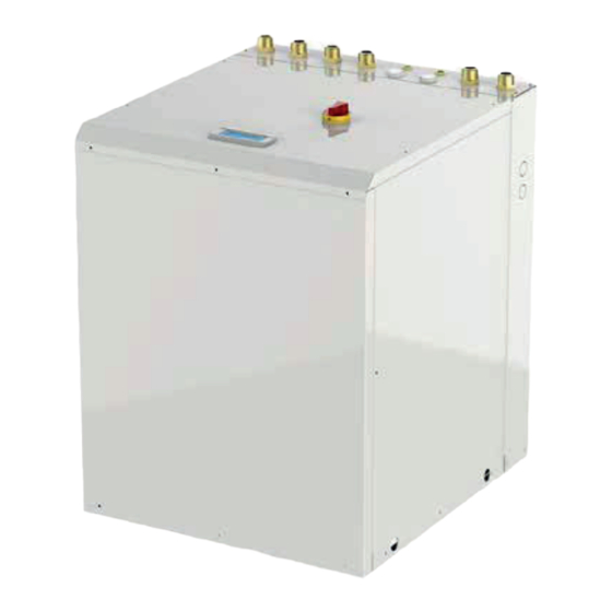
TECHNICAL SPECIFICATIONS UNIT DESCRIPTION The series heat pumps are particularly suitable for use in groundwater or geothermal probes. These units find their ideal application in combination with radiant panel heating systems or in all situations in which maximum efficiency is required in heating mode. The units have been designed to have an extremely efficient heating performance and can operate with a water temperature of up to 60°C. -
Page 13: Versions Available
TECHNICAL SPECIFICATIONS 3.1.11 Electronic thermostatic valve All the units are equipped with an electronic thermostatic valve, in order to optimise the functioning of the cooling circuit and to maximise the energy efficiency of the system in all operating conditions that can be implemented on the system. VERSIONS AVAILABLE All units are hot/cold reversible, with cycle inversion on the cooling circuit. -
Page 14: Description Of Accessories
TECHNICAL SPECIFICATIONS DESCRIPTION OF ACCESSORIES 3.3.1 GEO HFE 6-42 3.3.1 Rubber vibration dampers (KAVG) To be installed beneath the unit base and the ground to avoid the transmission of vibrations (and the noise) to the building. HFE06 HFE08 HFE12 HFE16 HFE20 HFE24 HFE33 HFE42 Function 3.3.2 RS485 serial interface card modbus protocol (INSE) It is used to monitor and supervise the machine... - Page 15 TECHNICAL SPECIFICATIONS WZA - WZA/RV 3.3.2 GEO HFS 60-100 Main switch HFS60 HFS80 HFS100 Function Microprocessor control It allows the delivery temperature of the conditioning system Mixing kit to be adjusted Water pumps Remote control web kit It is used to monitor and supervise the machine via the Internet LS low noise version LS00 It allows communication with supervision systems with the Modbus...
-
Page 16: Technical Data
TECHNICAL SPECIFICATIONS TECHNICAL DATA Modello GEO HFE / HFS WZA Model Winter operation (1) 5,76 7,54 10,2 13,2 17,1 21,0 25,4 33,8 48,8 64,6 85,4 Heat output 1,30 1,65 2,17 2,86 3,71 4,36 5,52 7,79 11,7 15,8 20,0 compressor power consumption 4,43 4,57 4,68... - Page 17 TECHNICAL SPECIFICATIONS WZA Model Modello GEO HFE / HFS Energy efficiency (5) Energy class in low temperature kWh/kWh 5,41 5,68 5,66 5,67 5,69 6,07 6,03 5,79 5,79 5,79 5,79 SCOP in low temperature 208,4 219,2 218,3 218,8 219,7 234,8 233,0 223,4 223,4 223,4...
- Page 18 TECHNICAL SPECIFICATIONS 3.4.1 Total electrical consumption Maximum values Electrical Geothermal Domestic hot Compressor System pump Total power supply pump water pump (V-Ph-Hz) F.L.I. F.L.A. L.R.A. L.R.A. F.L.I. F.L.A. F.L.I. F.L.A. F.L.I. F.L.A. F.L.I. F.L.A. L.R.A. L.R.A. cosphi (kW) (A)* (kW) (kW) (kW) (kW)
-
Page 19: Use Limits
TECHNICAL SPECIFICATIONS USE LIMITS Heating Cooling Source water outlet temperature (°C) Source water outlet temperature (°C) With the addition of an adequate quantity of glycol in With the addition of an adequate quantity of glycol in the source the utility circuit circuit GEO HFS 60-80-100 The nominal water flow refers to a temperature difference between input and output of the utility exchanger of 5°C. -
Page 20: Compressor Partialisation Steps
TECHNICAL SPECIFICATIONS COMPRESSOR PARTIALISATION STEPS NUMBER OF COMPRESSORS Model HFE 06 100% HFE 08 100% HFE 12 100% HFE 16 100% HFE 20 100% HFE 24 HFE 33 HFE 42 HFS 60 HFS 80 HFS 100 CORRECTION FACTORS 3.7.1 Glycol use correction factors Percentage of Freezing IPCF... -
Page 21: Sound Data
TECHNICAL SPECIFICATIONS SOUND DATA SOUND LEVEL dB (A) Modello 63 Hz 125 Hz 250 Hz 500 Hz 1.000 Hz 2.000 Hz 4.000 Hz 8.000 Hz HFE 06 47,0 10,0 28,0 37,0 32,0 37,0 34,0 HFE 08 48,0 12,0 29,0 32,0 31,0 39,0 31,0... -
Page 22: Installation
INSTALLATION GENERAL WARNINGS AND USE OF SYMBOLS Before carrying out any type of operation, each operator must be perfectly familiar with operation of the machine and its controls and must have read and understood all the information contained in this manual. All operations performed on the machine must be carried out by qualified personnel in compliance with the national legislation in force in the destination country The installation and maintenance of the machine must be carried out according to the national or local regulations in... -
Page 23: Receipt And Inspection
INSTALLATION RECEIPT AND INSPECTION When installing or servicing the unit, the rules indicated in this manual must be complied with, together with those on board the unit and, in any case, all necessary precautions must be taken. Failure to comply with these regulations may cause dangerous situations. On receiving the unit, check for any damage: the machine left the factory in perfect conditions;... -
Page 24: Unpacking
INSTALLATION UNPACKING The packaging could be dangerous for operators. It is advisable to leave the units packed during handling and to remove the packaging only at the time of installation. The unit's packaging must be removed carefully to avoid damaging the machine. The materials that compose the packaging can be of a mixed nature (wood, cardboard, nylon, etc.). -
Page 25: Positioning And Minimum Technical Spaces
INSTALLATION POSITIONING AND MINIMUM TECHNICAL SPACES All models are designed and built for indoor installation; it is therefore absolutely necessary to avoid installing the unit outdoors. It is good practice to create a support slab of sizes appropriate to those of the unit. The units transmit a low level of vibrations to the ground; it is in any case advisable to place the antivibration supports between the base frame and the support surface. -
Page 26: Hydraulic Connections
INSTALLATION HYDRAULIC CONNECTIONS 4.9.1 System side hydraulic connections Connections made by the manufacturer Connections to be performed by the installer System return System delivery 4.9.2 Domestic hot water side hydraulic connections Connections made by the manufacturer Connections to be performed by the installer High temperature water inlet for domestic hot water use... -
Page 27: Chemical Characteristics Of The Water
INSTALLATION 4.9.4 Well side hydraulic connections Connections made by the manufacturer Connections to be performed by the installer External water inlet Ref. Description Ref. Description Vent valve Discharge Expansion vessel Differential pressure switch Cut-off valve Circulation pump Mesh filter Pressure gauge Drain valve Thermometer Antivibration element... -
Page 28: Minimum Water Content Of Utility /Sanitary Circuit
INSTALLATION 4.11 MINIMUM WATER CONTENT OF UTILITY /SANITARY CIRCUIT The heat pump units require a minimum water content inside the utility/sanitary hydraulic circuit, in order to guarantee correct operation of the unit. Correct water content reduces the number of starts and stops of the compressors and therefore lengthens the operating life of the unit. -
Page 29: Typical Installations
INSTALLATION 4.14 TYPICAL INSTALLATIONS 4.14.1 Typical system layout for heating, cooling and domestic hot water production Ref. Ref. Description Description Ref. Ref. Description Description GEO HFE R heat pump (with recovery) Heat pump (with recovery) Fiorini thermal solar collectors Thermal solar collectors Geothermal circuit with inverter pump Geothermal circuit with inverter pump Thermal solar pumping unit... -
Page 30: Electrical Connections: Preliminary Safety Information
INSTALLATION The electrical panel is located inside the unit in the upper part of the technical compartment where the refrigerating circuit components are located. To access the electrical panel, remove the front panel of the unit. The electrical connection must be made according to the wiring diagram attached to the unit and in compliance with local and international regulations. -
Page 31: Electrical Data
INSTALLATION 4.16 ELECTRICAL DATA The following electrical data refer to the standard unit without accessories. In all other cases, refer to the electrical data shown in the annexed wiring diagrams. The supply voltage must not undergo variations of more than ±10% of the nominal value and the imbalance between the phases must be less than 1% according to the EN 60204 standard. - Page 32 INSTALLATION The power supply cable must be routed through one of the dedicated holes located on the left or right side of the machine, after removing the pre-cut part from the selected hole. Connect the cable to the terminals inside the electrical panel by passing it through the appropriate cable glands in the lower part of the panel. Auxiliary connection terminal board (The configuration of the electrical panel can change slightly depending on the size) After approximately 10 minutes of operation of the heat pump, check the tightness of the screws on the power supply...
- Page 33 INSTALLATION If required, it is possible to extend the connection cable by performing tin soldering suitably insulated for the junction of the wires. The length of the cable must not exceed 30 m and the section must not be less than 0.5 mm2 (the use of shielded cable is recommended). 4.17.3 Auxiliary connections The utility terminal board inside the electrical panel contains the terminals described below.
- Page 34 INSTALLATION Rif. Morsetti Descrizione Note Regulation probe See the previous paragraph. (utility return) Digital outputs Voltage contact for the geothermal pump control (230Vac, 1A maximum). Voltage contact for the geothermal pump control (230Vac, 1A maximum). Geothermal pump Geothermal pump The control is connected in the factory. In the HFE models the control is connected in the factory.
- Page 35 INSTALLATION Rif. Morsetti Descrizione Note Clean contact to indicate the operating mode of the heat pump - Closed = Winter Summer/Winter mode (maximum flow rate 230 Vac, 1 A) Clean contact to indicate the alarm status - Closed = Alarm (maximum flow rate 230 General alarm Vac, 1 A).
-
Page 36: Principle Cooling Layouts
INSTALLATION 4.18 PRINCIPLE COOLING LAYOUTS 4.18.1 Single compressor unit Ø Ø Ø Ø BTAS Ø Ø Ø Ø Ø Ø Ø Ø Ø Ø Ø Ø Ø User 4.18.2 Double compressor unit Ø Ø Ø Ø Ø Ø BTAS Ø Ø... -
Page 37: Start-Up
START UP PRELIMINARY CHECKS Before starting the machine it is necessary to carry out preliminary checks on the electrical, hydraulic and cooling parts. Commissioning operations must be carried out in compliance with all the provisions of the preceding paragraphs. Never switch off the unit (for temporary shutdown) by opening the main switch: this device must only be used to disconnect the power supply unit in the absence of current flow, for example when the unit is OFF . -
Page 38: Operating Characteristics
START UP 5.1.2 Calibration of control components Device Set-point Differential Reset type Heating mode °C ----- Domestic hot water or recovery mode °C ----- Cooling mode °C ----- Frost protection thermostat Manual °C Source pressure switch Manual 38,5 Low pressure switch Manual Water safety valve Automatic... -
Page 39: Control Panel
START UP CONTROL PANEL The control panel consists of a display and of programming keys 00/00/00 00:00 OPERATION ON/OFF MODE SUMMER/DHW ONLY/WINTER UNIT ON/OFF 5.3.1 Display 1st line Flashing date-time 00/00/00 - 00:00 Operation machine on 2nd line machine off Mode Summer In cooling function with domestic hot water supply... -
Page 40: Procedures
START UP PROCEDURES On the machine: • Set the main system switch to ON. • Set the main door-lock switch to ON. • The control panel display lights up. On the Control Panel: • Set the language of the control panel. In case of geothermal probe: •... -
Page 41: Utility Use
UTILITY USE MAIN FUNCTIONS 6.1.1 Start-up On the Control Panel: - Select Mode. - Select “Operation”: On. - The PRG button flashes for 3 min. (compressor delay) then remains on. 6.1.2 Seasonal change On the Control Panel: - Select "Mode". - Choose the operating mode from: Summer, Winter, domestic hot water only. -
Page 42: User Pages Display
UTILITY USE USER PAGES DISPLAY Funzionamento Home page where the heat pump is switched on or off and the system mode is chosen Modalita’ Inverno (winter, summer or domestic hot water). Spenta da tastiera 21/12/12 11:22 Pompa di calore CHiamata attesa Display of heat pump parameters, the type of call is the type of operation that the heat Tipo setpoint impianto pump is performing (system in winter, summer or domestic hot water). -
Page 43: Unit Maintenance
UNIT MAINTENANCE GENERAL WARNINGS From 01 January 2016, the new European Regulation 517_2014, “ Obligations arising in relation to the containment, use, recovery and destruction of fluorinated greenhouse gases used in stationary refrigeration, air conditioning and heat pump equipment ” became enforceable. The unit in question is subject to the regulatory obligations listed below, which must be carried out by all operators: a) Keep the equipment register b) Correct installation, maintenance and repair of the equipment... -
Page 44: Scheduled Maintenance
UNIT MAINTENANCE SCHEDULED MAINTENANCE The user must ensure that the unit undergoes adequate maintenance based on what is indicated in the Manual and what is prescribed by the laws and local regulations in force. The user must ensure that the unit undergoes adequate inspections, controls and periodic maintenance, based on the type, size, age and function of the system and on what is indicated in the Manual. - Page 45 UNIT MAINTENANCE 7.4.1 Electrical system and control devices Frequency Operations to be performed Every Every Every When month 6 months year required Check that the unit is working properly and that there are no alarms Inspect the unit visually Check the noise and vibration of the unit Check the functionality of the safety devices and interlocks Check the performance of the unit Check the electrical consumption of the various utilities (compressors, fans, etc.)
-
Page 46: Cooling Circuit Repair
UNIT MAINTENANCE 7.4.3 Compressors Frequency Operations to be performed Every Every Every When month 6 months year required Inspect the compressors visually Check the noise and vibrations of the compressors Check the supply voltage of the compressors Check the electrical connections of the compressors Check the oil level in the compressors by means of the dedicated light (if present) Check that the casing heaters are powered and working properly (if present) Check the condition of the electrical cables of the compressors and their fixing in the terminals... -
Page 47: Decommissioning
DECOMMISSIONING Disconnecting the unit All the decommissioning operations must be performed by qualified personnel in compliance with the national legislation in force in the destination country. • Avoid spills or leaks of any fluid into the environment. • Before disconnecting the machine recover if present: - the refrigerant gas;... -
Page 48: Diagnosis And Troubleshooting
DIAGNOSIS AND TROUBLESHOOTING Troubleshooting All the units are controlled and tested at the factory before shipment, however it is possible that some anomaly or failure may occur during operation. The following are the indications necessary to identify the causes of the most common cases. IT IS ADVISABLE TO RESET AN ALARM ONLY AFTER REMOVING THE CAUSE THAT HAS GENERATED IT;... -
Page 49: Possible Anomalies And Possible Remedies
DIAGNOSIS AND TROUBLESHOOTING Problem Description Cause Outdoor air probe error Outdoor air temperature probe with incorrect Temperature probe cable interrupted or disconnected. reading Compressor intake probe Compressor intake temperature probe with Temperature probe cable interrupted or disconnected. error incorrect reading Possible anomalies and possible remedies Problem Description... - Page 50 DIAGNOSIS AND TROUBLESHOOTING Problem Description Cause High intake pressure - Well water high temperature or geothermal ring in - Check winter or domestic hot water mode - High water inlet temperature of the system in - Check summer mode - Thermostatic expansion valve faulty - Check and replace the component if necessary The compressor stops - Excessive delivery pressure...
Need help?
Do you have a question about the WZA Series and is the answer not in the manual?
Questions and answers