
Related Manuals for HIdRos LZT P2U Series


Summary of Contents for HIdRos LZT P2U Series
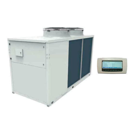
- Page 1 HIGH EFFICIENCY AIR TO WATER HEAT PUMPS WITH E.V.I. COMPRESSORS LZT P2U/P2S SERIES TECHNICAL MANUAL Multiple instructions: the instructions before the unit Rev. A 10-2021...
- Page 2 LZT P2U/P2S Declaration of conformity MTEC.5001.GB-A-1 Operation and maintenance manual LZT series English Rev. A 10-2021...
-
Page 3: Table Of Contents
LZT P2U/P2S INDEX 1. INTRODUCTION ..............................................................................................................................................................................................................................................................................................................................................2. SAFETY ..................................................................................................................................................................................................................................................3.2 Other versions ............................................................................................................................................................................................................. 3.9 C .................................................................. - Page 4 LZT P2U/P2S 5. UNIT START UP ............................................................................................................................6. USE ....................................................................... 6.2 Stop .................................................................................................................................... 6.6 CIRC ................................................................................................................................... 7. UNIT MAINTENANCE ................................................................................................................................................................................................. 8. DECOMMISSIONING ....................................................................................................................
-
Page 5: Introduction
LZT P2U/P2S 1. INTRODUCTION 1.1 Preliminary information these instructions. 1.2 Aim and content of the manual instructions. 1.3 How to store this manual user. 1.4 Manual Update 1.5 How to use this manual MTEC.5001.GB-A-1 Operation and maintenance manual LZT series English Rev. - Page 6 LZT P2U/P2S 1.6 Potential Risks POTENTIAL LOCATION OF METHOD OF INJURY PRECAUTIONS RISK RISK Burns. severe burns. unit enclosure severe burns. unit. severe burns. open. Entire unit Entire unit MTEC.5001.GB-A-1 Operation and maintenance manual LZT series English Rev. A 10-2021...
- Page 7 LZT P2U/P2S 1.7 General Description of Symbols Used BANNED WARNING ACTION REQUIRED MTEC.5001.GB-A-1 Operation and maintenance manual LZT series English Rev. A 10-2021...
- Page 8 LZT P2U/P2S 1.8 Safety symbols used GENERAL RISK ELECTRICAL HAZARD MOVING PARTS HOT SURFACES SHARP SURFACES EARTH CONNECTION READ AND UNDERSTAND THE INSTRUCTIONS RECOVER OR RECYCLE MATERIAL 1.9 Limitations and prohibited use MTEC.5001.GB-A-1 Operation and maintenance manual LZT series English Rev.
- Page 9 LZT P2U/P2S Manufacturer: PD322111 +39 049 9731022 123456 1LZT.0302.NNRV2U-1A Modello Matricola Model Serial number 3/2017 Categoria PED Data di fabbricazione PED Category Manifacture date R410A 2088 Tipo refrigerante Gruppo fluido Refrigerant type Fluid group 10 Kg 10 Kg 20,88 ton 20,88 ton Carica refrigerante Equivalente...
-
Page 10: Safety
LZT P2U/P2S 2. SAFETY 2.1 Warning re potentially hazardous toxic substances • • ENVIRONMENTAL PROTECTION : 2.1.3 Persistence and degradation 2000. 2.1.4 Effects of discharges 2.1.5 Exposure controls and personal protection 2.1.6 Professional exposure limits R410A 2.2 Refrigerant handling MTEC.5001.GB-A-1 Operation and maintenance manual LZT series English Rev. - Page 11 LZT P2U/P2S 2.3 Prevent inhalation of high vapor concentration 2.4 Procedures to be adopted in the event of accidental release of refrigerant 2.5 Main Toxicological Information Regarding the Type of refrigerant used 2.5.1 Inhalation 2.5.2 Contact with skin 2.5.3 Contact with eyes 2.5.4 Ingestion 2.6 First Aid Measures 2.6.1 Inhalation...
- Page 12 LZT P2U/P2S 3. TECHNICAL CHARACTERISTICS 3.1 Unit description 3.1.1 Frame 3.1.2 Refrigerant circuit 3.1.3 Compressors 3.1.4 Source heat exchanger 3.1.5 Fans 3.1.6 User heat exchangers protection. MTEC.5001.GB-A-1 Operation and maintenance manual LZT series English Rev. A 10-2021...
-
Page 13: Other Versions
LZT P2U/P2S 3.1.7 Electric enclosure 3.1.8 Microprocessors 3.1.9 Control and protection devices 3.2 Other versions 3.2.1 Version HH 3.2.2 Version RV 3.2.3 SA Version 3.2.4 SE Version 3.2.5 HA Version 3.2.6 HE Version 3.2.7 Version LS MTEC.5001.GB-A-1 Operation and maintenance manual LZT series English Rev. - Page 14 LZT P2U/P2S 3.2.8 Version XL 3.2.9 Version NN 3.2.10 Version P2U 3.2.11 Version P2S 3.3 Accessories description 3.3.1 Condensate discharge drip tray with antifreeze heater (BRCA) 3.3.2 Antifreeze kit (RAEV2, RAEV4) 3.3.3 Rubber vibration dampers (KAVG) 3.3.4 RS485 serial interface card modbus protocol (INSE) (Standard for SE / HE versions) 3.3.6 Electronic expansion valve (VTEE) 3.3.7 Electronic soft starter (DSSE)
- Page 15 LZT P2U/P2S 3.3.8 Remote control panel (PCRL) 3.3.9 Hydraulic circuit antifreeze kit (KP) 3.3.10 Hydraulic kit with one pump without tank - user circuit (A1NTU) 3.3.11 Hydraulic kit with two pumps without tank - user circuit (A2NTU) 3.3.12 Cascade control system (SGRS) MTEC.5001.GB-A-1 Operation and maintenance manual LZT series English Rev.
- Page 16 LZT P2U/P2S 3.4 What is the E.V.I. technology (enhanced vapour injection) m +i Pm+i Water production at 40°C Water production at 40°C C.O.P. Water production at 55°C Water production at 55°C Ambient temperature (°C) Max Water Temperature (°C) Ambient temperature (°C) MTEC.5001.GB-A-1 Operation and maintenance manual LZT series English Rev.
- Page 17 LZT P2U/P2S 1002 1202 SA/LS/HH - P2S/P2U 1002 1202 SE/LS/HH - P2S/P2U R410A R410A R410A R410A R410A R410A R410A R410A R410A 2088 2088 2088 2088 2088 2088 2088 2088 2088 1002 1202 HA/LS/HH - P2S/P2U 1002 1202 HE/LS/HH - P2S/P2U R410A R410A R410A...
- Page 18 LZT P2U/P2S 1002 1202 HA/XL/HH - P2S/P2U 1002 1202 HE/XL/HH - P2S/P2U R410A R410A R410A R410A R410A R410A R410A R410A R410A 2088 2088 2088 2088 2088 2088 2088 2088 2088 1002 1202 HE/NN/HH - P2S/P2U R410A R410A R410A R410A R410A R410A R410A R410A...
- Page 19 LZT P2U/P2S 1002 1202 SA/LS/RV - P2S/P2U 1002 1202 SE/LS/RV - P2S/P2U R410A R410A R410A R410A R410A R410A R410A R410A R410A 2088 2088 2088 2088 2088 2088 2088 2088 2088 1002 1202 HA/LS/RV - P2S/P2U 1002 1202 HE/LS/RV - P2S/P2U R410A R410A R410A...
- Page 20 LZT P2U/P2S 1002 1202 HA/XL/RV - P2S/P2U 1002 1202 HE/XL/RV - P2S/P2U R410A R410A R410A R410A R410A R410A R410A R410A R410A 2088 2088 2088 2088 2088 2088 2088 2088 2088 1002 1202 HE/NN/RV - P2S/P2U R410A R410A R410A R410A R410A R410A R410A R410A...
- Page 21 LZT P2U/P2S 3.6 Operation limits - 20 - 10 3.6.2 User hot water temperature (Winter operation) the unit. 3.6.3 Cold water temperature (RV versions Only) 3.6.4 Ambient air temperature MTEC.5001.GB-A-1 Operation and maintenance manual LZT series English Rev. A 10-2021...
- Page 22 LZT P2U/P2S MTEC.5001.GB-A-1 Operation and maintenance manual LZT series English Rev. A 10-2021...
- Page 23 LZT P2U/P2S 3.7 Domestic hot water production 3.7.1 Solution 1 MTEC.5001.GB-A-1 Operation and maintenance manual LZT series English Rev. A 10-2021...
- Page 24 LZT P2U/P2S 3.7.2 Solution 2 This is the solution for existing buildings or for those applications where it is not possible to remove existing plants. possibility of using the existing DHW tank. COLD WATER in the tank. AS MUCH AS POSSIBLE MTEC.5001.GB-A-1 Operation and maintenance manual LZT series English Rev.
- Page 25 LZT P2U/P2S 3.8 Compressor capacity steps NUMBER of COMPRESSORS Model 1002 1202 3.9 Correction tables 3.9.1 Operation with glycol Glycol percentage Freezing point (°C) IPCF WFCF PDCF -3.2 0.985 1.02 1.08 -7.8 0.98 0.99 1.05 1.12 -14.1 0.97 0.98 1.09 1.22 -22.3 0.965...
- Page 26 LZT P2U/P2S 3.10 Sound data SA / LS Octave bands (Hz) Mod. dB(A) dB(A) SE / LS HA / LS HE / LS MTEC.5001.GB-A-1 Operation and maintenance manual LZT series English Rev. A 10-2021...
- Page 27 LZT P2U/P2S HA / XL Octave bands (Hz) Mod. dB(A) dB(A) HE/ XL HE / NN Octave bands (Hz) Mod. dB(A) dB(A) MTEC.5001.GB-A-1 Operation and maintenance manual LZT series English Rev. A 10-2021...
- Page 28 LZT P2U/P2S 4. INSTALLATION 4.1 General safety guidelines and and use of symbols 4.2 Health and safety Considerations 4.3 Personal protective equipment MTEC.5001.GB-A-1 Operation and maintenance manual LZT series English Rev. A 10-2021...
-
Page 29: Inspection
LZT P2U/P2S 4.4 Inspection In Case of Damage 4.5 Storage 4.5.1 Shipment 4.6 Unpacking MTEC.5001.GB-A-1 Operation and maintenance manual LZT series English Rev. A 10-2021... - Page 30 LZT P2U/P2S 4.7 Lifting and handling 4.8 Location and minimum technical clearances MTEC.5001.GB-A-1 Operation and maintenance manual LZT series English Rev. A 10-2021...
- Page 31 LZT P2U/P2S SA-SE 252 - 302 SA/SE 432 - 492 - 592 SA/SE 752 - 852 SA/SE 1002 - 1202 HA-HE/LS-XL 252 - 302 HA-HE/LS-XL 432 - 492 HA-HE/LS-XL 592 - 602 - 752 - 852 - 1002 - HE/NN 1002 - 1202 HA-HE/NN 252 HA-HE/NN 312 1202...
- Page 32 LZT P2U/P2S 4.9 Installation of rubber vibration dampers (KAVG) sez A - A ØM ØD ØE Mod. 252÷312 432÷602 752÷1202 4.10 Serial interface card RS485 (INSE) Supervision MTEC.5001.GB-A-1 Operation and maintenance manual LZT series English Rev. A 10-2021...
- Page 33 LZT P2U/P2S 4.11 Installation of condensate drip tray (BRCA) 4.11.1 Installation of the heating cable MTEC.5001.GB-A-1 Operation and maintenance manual LZT series English Rev. A 10-2021...
- Page 34 LZT P2U/P2S 4.12 Hydraulic connections • • • • • • Heating mode: Cooling mode: 4.13 Chemical characteristics of the water Total Hardness Electric conductibility Sulphur ion None Chlorine ions Ammonia ion None Sulphuric acid ions Silicon ion Total Iron MTEC.5001.GB-A-1 Operation and maintenance manual LZT series English Rev.
- Page 35 LZT P2U/P2S 4.14 Hydraulic components 4.14.1 P2S Versions P2U Versions User Circuit 4.14.2 P2S Versions + A1NTU/A2NTU P2U Versions + A1NTU/A2NTU User Circuit MTEC.5001.GB-A-1 Operation and maintenance manual LZT series English Rev. A 10-2021...
- Page 36 LZT P2U/P2S 4.15 User circuit minimum water content Model 852 1002 1202 Minimum water content winter mode (l) 890 1025 4.16 Minimum domestic hot water circuit content 852 1002 1202 Modell Minimum water content 890 1025 hydraulic circuit (l) The above values do not guarantee the availability and temperature of domestic hot water 4.17 Filling the hydraulic circuit •...
- Page 37 LZT P2U/P2S 4.19 Typical installations 4.19.1 Combined heating / Cooling / Domestic hot water production – 2 pipe system P2S User circuit sensor The plant components supplied by the company are: STANDARD OPTIONS NOT AVAILABLE User circuit sensor MTEC.5001.GB-A-1 Operation and maintenance manual LZT series English Rev.
- Page 38 LZT P2U/P2S 4.20 Electric connections: preliminary safety information FROST PROTECTION MTEC.5001.GB-A-1 Operation and maintenance manual LZT series English Rev. A 10-2021...
- Page 39 LZT P2U/P2S 4.21 Electric data 4.21.1 Electric data LS / XL models Models LS / XL 1002 1202 Power supply Control board Auxiliary circuit Fans power supply Line section PE section 4.21.2 Electric data NN model Model NN 1002 1202 Power supply Control board Auxiliary circuit...
-
Page 40: Electric Connections
LZT P2U/P2S 4.22 Electric connections 4.22.1 Power supply and electrical connections 4.22.2 Remote wiring connections (compulsory) USER CIRCUIT WATER INLET SENSOR (BTI) USER CIRCUIT WATER PUMP DOMESTIC HOT WATER SENSOR (BTS) MTEC.5001.GB-A-1 Operation and maintenance manual LZT series English Rev. A 10-2021... - Page 41 LZT P2U/P2S DOMESTIC HOT WATER CIRCUIT PUMP 4.22.3 Remote wiring connections (optional) 3 WAY ON/OFF VALVE REMOTE ON / OFF REMOTE SUMMER / WINTER CHANGE OVER REMOTE GENERAL ALARM 90-91-92. USER CIRCUIT ELECTRIC INTEGRATION HEATERS DOMESTIC HOT WATER ELECTRIC INTEGRATION HEATERS PRIORITY SELECTOR (Hot water) MTEC.5001.GB-A-1 Operation and maintenance manual LZT series English Rev.
- Page 42 LZT P2U/P2S HEATING CABLE WEATHER COMPENSATED SENSOR (BTE) USER CIRCUIT WATER OUTLET SENSOR (BTO) USER CIRCUIT FLOW SWITCH (SFW1) MTEC.5001.GB-A-1 Operation and maintenance manual LZT series English Rev. A 10-2021...
- Page 43 LZT P2U/P2S 4.23 Positioning of the user circuit water inlet sensor (BTI) Correct positioning of the BTI sensor Incorrect positioning of the BTI sensor 4.24 Positioning of the domestic hot water circuit sensor (BTS) Correct positioning of the BTS sensor Incorrect positioning of the BTS sensor MTEC.5001.GB-A-1 Operation and maintenance manual LZT series English Rev.
- Page 44 LZT P2U/P2S 4.25 Refrigerant circuit layout P2U Version P2S Version EXV 2 EXV 1 EXV 4 MTEC.5001.GB-A-1 Operation and maintenance manual LZT series English Rev. A 10-2021...
- Page 45 LZT P2U/P2S P2U Version P2S Version EXV 2 EXV 3 EXV 1 EXV 4 MTEC.5001.GB-A-1 Operation and maintenance manual LZT series English Rev. A 10-2021...
-
Page 46: Unit Start Up
LZT P2U/P2S 5. UNIT START UP 5.1 Preliminary checks 5.1.1 Before start-up • • • • • • • • • • • • • MTEC.5001.GB-A-1 Operation and maintenance manual LZT series English Rev. A 10-2021... - Page 47 LZT P2U/P2S 5.1.2 Device Set-point Differential Reset Device Set-point Differential Reset ----- ----- ----- 5.1.3 Controls during unit operation • • • MTEC.5001.GB-A-1 Operation and maintenance manual LZT series English Rev. A 10-2021...
- Page 48 LZT P2U/P2S 5.2 Position of the control panel Unit ON: Heating Unit ON: Heating 00:00 01/01/2014 30.0 °C Evaporator inlet temperature 35.0 °C Evaporator outlet temperature °C External air temp. (FC) San. water temperature 50.0 °C PROBES ALARM SERVICE CIRC. 5.2.1 Display icons Icon Meaning...
- Page 49 LZT P2U/P2S 5.2.2 Key function PROBES ALARM SERVICE CIRC Stand-by Stand-by 00:00 01/01/2014 Evaporator inlet temperature 30.0 °C Evaporator outlet temperature °C 35.0 External air temp. (FC) °C San. water temperature 50.0 °C PROBES ALARM SERVICE CIRC. 5.3 How to remote the control 5.3.2 Remote keyboard connection (VGI890) ENTER Rosso / Red...
- Page 50 LZT P2U/P2S 5.3.2 Panel mounting connection diagram 5.3.3 Wall mounting connection diagram 5.4.4 Selection built in display or remote keyboard ENTER ENTER Remoto MTEC.5001.GB-A-1 Operation and maintenance manual LZT series English Rev. A 10-2021...
-
Page 51: Use
LZT P2U/P2S 6. USE 6.1 Switch the unit on Unit 6.1.1 Switch the unit on from the keyboard Cooling mode Heating mode Domestic hot water mode 5.3.1 Selection built in display or remote keyboard MTEC.5001.GB-A-1 Operation and maintenance manual LZT series English Rev. -
Page 52: Stop
LZT P2U/P2S 6.1.2 Heating and cooling mode HEATING MODE Unit ON: Heating Unit ON: Heating Unit ON: Cooling Unit ON: Cooling 00:00 01/01/2014 00:00 01/01/2014 Evaporator inlet temperature 28.4 °C Evaporator inlet temperature 20.2 °C Evaporator outlet temperature °C Evaporator outlet temperature °C 27.0 63.6... - Page 53 LZT P2U/P2S 6.3 Set point SET. Set point Set point Stand-by Stand-by 00:00 01/01/2014 Energy saving Evaporator inlet temperature 30.0 °C Dynamic set Heating 35.0 °C Evaporator outlet temperature 35.0 °C Sanitary water 50.0 °C External air temp. (FC) °C San.
- Page 54 LZT P2U/P2S 6.4 PROBES key PROBES Stand-by Stand-by 00:00 01/01/2014 Evaporator inlet temperature 30.0 °C Evaporator outlet temperature 35.0 °C External air temp. (FC) °C San. water temperature 50.0 °C PROBES ALARM SERVICE CIRC. Probes visualization Probes visualization Probes visualization Probes visualization Evaporator inlet temperature San.
-
Page 55: Circ
LZT P2U/P2S • Reset: RESET • Password • Active RST/ALL 6.6 CIRC key CIRC ENTER State of the compressors Color black: Color white: level of step control. Unit ON: Heating Unit ON: Heating 00:00 01/01/2014 Evaporator inlet temperature 28.4 °C Evaporator outlet temperature 27.0 °C... - Page 56 LZT P2U/P2S Unloading status Unloading status Compressor status Compressor status Circuit 1 Circuit 1 Circuit 1 Circuit 1 unloading not ongoing 51 % Circuit 2 Circuit 2 Circuit 2 Circuit 2 ALARM EXIT ALARM EXIT Evaporating-condensing probe Evaporating-condensing probe Evaporator pump status Evaporator pump status Evap.
- Page 57 LZT P2U/P2S 6.7 SERVICE key ENTER EXIT ENTER EXIT Press the SERVICE ENTER SET to select Press the EXIT MTEC.5001.GB-A-1 Operation and maintenance manual LZT series English Rev. A 10-2021...
- Page 58 LZT P2U/P2S 6.7.1 Service parameters setting ENTER. 1st level password (Pr1) 1st level password (Pr1) ALARM EXIT 1st level password (Pr1) 1st level password (Pr1) Password OK! Press ENTER to continue ALARM ENTER EXIT Press Code Meaning Code Meaning Set point Defrost MTEC.5001.GB-A-1 Operation and maintenance manual LZT series English Rev.
- Page 59 LZT P2U/P2S T1 or Parameter group selection Parameter group selection St01 10.0 °C St02 °C 15.0 °C St03 St04 40.0 °C Set point Set point Summer set point Summer set point ALARM ENTER EXIT ALARM EXIT Parameter group selection Parameter group selection Sd01 °C Sd02...
- Page 60 LZT P2U/P2S Weather compensated function Heating mode Cooling mode MTEC.5001.GB-A-1 Operation and maintenance manual LZT series English Rev. A 10-2021...
- Page 61 LZT P2U/P2S Parameter group selection Parameter group selection FS02 FS03 45.0 °C FS04 °C Sanitary circuit Sanitary circuit Sanitary water priority Sanitary water priority ALARM ENTER EXIT ALARM EXIT 6.7.2 Time bands setting ES01 0 24 ES17 ES02 0 24 ES18 ES03 0 24...
- Page 62 LZT P2U/P2S Operating modes • Automatic ON-OFF: • Energy Saving: Parameter group selection Parameter group selection ES01 ES01 18:00 18:00 Time band n°1 Time band n°1 ES02 ES02 00:00 00:00 Time band n°2 Time band n°2 ES03 ES03 05:00 05:00 Time band n°3 Time band n°3 Energy Saving...
- Page 63 LZT P2U/P2S 6.7.2 Setting date and time ENTER. Press T2 to set the Clock setting Clock setting : 07 Energy saving Energy saving Disabled Disabled Data setting Data setting 05 / 7 / 14 ON/OFF scheduling ON/OFF scheduling Disabled Disabled Dat of the week Dat of the week Tuesday...
- Page 64 LZT P2U/P2S 6.7.3 Compressor maintenance ENTER. ENTER ENB/DIS Circuito 1 Circuito 1 Circuit 1 Circuit 1 Compressor mainteinance Compressor mainteinance Status Hour Start-up Reset Comp 1 Comp 1 Comp 1 abilitato enabled Circuit 1 Circuit 2 ALARM ENTER EXIT ALARM ENB/DIS EXIT 6.7.4 Water pumps...
- Page 65 LZT P2U/P2S 6.7.6 Alarms ENTER. Alarms Alarms b1HP b1HP Attivo Active Aktiv Clock alarm RST ALL RESET EXIT 6.7.7 Alarm log ENTER. RST ALL Alarm log Alarm log b1HP b1HP High pressure circuit 1 b1AC b1AC Antifreeze circuit 1 in summer mode ALARM RST ALL EXIT...
- Page 66 LZT P2U/P2S Press Defrost circ. 1: Defrost circ. 1: cycle not in progress Defrost circ. 1: Defrost circ. 1: cycle not in progress Condenser 1 probe Condenser 1 probe Defrost end set Defrost end set 36.2 bar 36.2 bar Evaporator 1 probe Evaporator 1 probe Combined defrost probe Combined defrost probe...
- Page 67 LZT P2U/P2S 6.7.11 Screw compressor (If available) ENTER. ENTER Screw compressors Screw compressors Screw compressors circ. 1 Screw compressors circ. 1 Discharge temperature Discharge temperature 86.0 °C Disch.temp.alarm Disch.temp.alarm 100.0 °C 10.0 °C Liquid injection valve Liquid injection valve Liquid inject. set Liquid inject.
- Page 68 LZT P2U/P2S 6.7.13 Sanitary water ENTER. . Press SET Sanitary water: Sanitary water: Antilegionella cycle: disabled Antilegionella cycle: disabled Sanitary water temp. Sanitary water temp. 44.9 °C 45.3 °C Sanitary water Set point Antilegionella set point 50.0 °C 60.0 °C Real san.
- Page 69 LZT P2U/P2S 6.8 Acoustic signal silencing 6.9 Emergency Stop 6.9.1 Start after an emergency stop MTEC.5001.GB-A-1 Operation and maintenance manual LZT series English Rev. A 10-2021...
-
Page 70: Unit Maintenance
LZT P2U/P2S 7. MAINTENANCE OF THE UNIT 7.1 General warnings • • • 7.2 Drive access MTEC.5001.GB-A-1 Operation and maintenance manual LZT series English Rev. A 10-2021... - Page 71 LZT P2U/P2S 7.3 Scheduled maintenance Search for leaks CASE Visual Inspection Pressure Test 7.4 Periodical checks MTEC.5001.GB-A-1 Operation and maintenance manual LZT series English Rev. A 10-2021...
- Page 72 LZT P2U/P2S 7.4.1 Electrical system and adjustment Frequency Action to be performed As neces- 7.4.2 Condensing coils and fans Frequency Action to be performed As neces- present every three months or more MTEC.5001.GB-A-1 Operation and maintenance manual LZT series English Rev.
- Page 73 LZT P2U/P2S 7.4.3 Compressors Frequency Action to be performed As neces- service. 7.5 Refrigerant circuit repair Therefore: • • • • • • MTEC.5001.GB-A-1 Operation and maintenance manual LZT series English Rev. A 10-2021...
-
Page 74: Decommissioning
LZT P2U/P2S 8. DECOMMISSIONING 8.1 Disconnect the unit • • • • • 8.2 Disposal, recovery and recycling 8.3 RAEE Directive (only UE) MTEC.5001.GB-A-1 Operation and maintenance manual LZT series English Rev. A 10-2021... - Page 75 LZT P2U/P2S 9. DIAGNOSIS AND TROUBLESHOOTING Code Alarm Description Cause Solution ACF1 ACF2 ACF3 ACF4 ACF5 ACF6 ACF7 ACF8 ACF9 AEFL AEUn AHFL MTEC.5001.GB-A-1 Operation and maintenance manual LZT series English Rev. A 10-2021...
- Page 76 LZT P2U/P2S Code Alarm Description Cause Solution sensor AP10 sensor sensor sensor. sensor sensor. AtE1 AtE2 Restore the correct user circuit B1 HP b1AC b1AH b1dF b1hP circuit 1 B1LP b1lP circuit 1 MTEC.5001.GB-A-1 Operation and maintenance manual LZT series English Rev.
- Page 77 LZT P2U/P2S b1tF C1tr C2tr MTEC.5001.GB-A-1 Operation and maintenance manual LZT series English Rev. A 10-2021...
- Page 78 LZT P2U/P2S MTEC.5001.GB-A-1 Operation and maintenance manual LZT series English Rev. A 10-2021...
- Page 79 LZT P2U/P2S MTEC.5001.GB-A-1 Operation and maintenance manual LZT series English Rev. A 10-2021...
- Page 80 HIDROS Srl...
Need help?
Do you have a question about the LZT P2U Series and is the answer not in the manual?
Questions and answers