Table of Contents
Advertisement
Quick Links
FT722 & FT742 – Digital (RS485) Wind Sensor Manual
Flat-Front & Pipe-Mounted Variants
FT TECHNOLOGIES LTD.
TEL: +44 (0)20 8943 0801
SUNBURY HOUSE
FAX: +44 (0)20 8943 3283
BROOKLANDS CLOSE
www.fttechnologies.com
SUNBURY-ON-THAMES
E-MAIL: info@fttechnologies.com
MIDDLESEX TW16 7DX
A4266-4-EN
February 2019
The FT and Acu-Res logos are registered trademarks of FT Technologies Ltd.
Copyright © 2019 FT Technologies Ltd. All rights reserved.
Advertisement
Table of Contents

Related Manuals for FT Technologies acures FT722


Summary of Contents for FT Technologies acures FT722
- Page 1 SUNBURY HOUSE FAX: +44 (0)20 8943 3283 BROOKLANDS CLOSE www.fttechnologies.com SUNBURY-ON-THAMES E-MAIL: info@fttechnologies.com MIDDLESEX TW16 7DX A4266-4-EN February 2019 The FT and Acu-Res logos are registered trademarks of FT Technologies Ltd. Copyright © 2019 FT Technologies Ltd. All rights reserved.
-
Page 2: Table Of Contents
Section 1 Introduction Contents Product Symbols ...................... 4 Safety Instructions ....................5 Consignes de Sécurité ..................... 6 INTRODUCTION ....................7 Product Overview ........................ 7 Build Versions and Labelling ..................... 7 Scope of Use ........................7 Major Changes Compared to Previous FT702LT Digital Products ......... 8 FT722 and FT742 differences ..................... - Page 3 Section 1 Introduction 4.4.3 Command Line Terminal Programs (Including Tera Term) ..........47 SENSOR COMMUNICATION ................49 Introduction ........................49 RS485 Protocol ........................49 Configuring the Sensor ..................... 50 Communication ........................50 5.4.1 Conventions used in this manual ..................50 5.4.2 Data Transmission ......................
-
Page 4: Product Symbols
Cela doit être fait par le should be done by returning the product to retour du produit à FT Technologies FT Technologies or by using an appropriate ou en utilisant une entreprise waste disposal company. This product d'élimination de déchets. Ce produit should not be disposed of in general waste ne doit pas être éliminé... -
Page 5: Safety Instructions
In accordance with the instructions set out in this manual, observing all information, warnings and instructions In accordance with any other instructions or guidance FT Technologies provide • To ensure that the product remains compliant with the electrical safety requirements of the UL / CSA 61010-1 Standards it must be;... -
Page 6: Consignes De Sécurité
Conformément aux instructions figurant dans ce manuel et en observant toutes les informations, avertissements et instructions Conformément à d'autres instructions ou directives que FT Technologies fournit Pour garantir que le produit reste compatible avec les exigences de sécurité électrique de l'UL/CSA 61010-1 normes, l'équipement doit être;... -
Page 7: Introduction
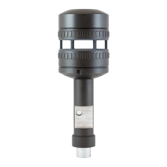
Section 1 Introduction 1 INTRODUCTION 1.1 Product Overview The FT722 and FT742 are solid-state ultrasonic wind sensors using a patented Acoustic Resonance airflow sensing technique to measure accurately both wind speed and direction. The sensors have been specifically designed to operate in harsh environments including offshore, lightning and ice-prone areas. The wind sensor has no moving parts to degrade or wear-out and is designed for applications requiring high reliability. -
Page 8: Major Changes Compared To Previous Ft702Lt Digital Products
The Purchaser assumes all risks and liability in conjunction with the use of the information given. Any warranty given by FT Technologies in respect of the Equipment is conditional upon the sensor being handled, installed, integrated and operated in accordance within the guidelines given in this manual. -
Page 9: Functional Description
Section 2 Functional Description 2 FUNCTIONAL DESCRIPTION 2.1 Technical Performance 1 & 2 Sensor Performance Measurement Principle Acoustic Resonance (compensated against variations in temperature, pressure and humidity) Wind speed Measurement FT722 FT742 Range 0-50m/s 0-75m/s Resolution 0.1m/s 0.1m/s Accuracy ±0.3m/s (0-16m/s) ±0.3m/s (0-16m/s) ±2% (16m/s-40m/s) ±2% (16m/s-40m/s) - Page 10 4. The heater set point, current, operational voltage and maximum power limits can be configured at the factory or by programming the sensor’s internal parameter settings, see Sections 6.4.15 and 6.4.17, or contact FT technologies for further information 5. Acoustic Temperature accuracy can be affected by the wind sensor heater – user calibration may be required FT722 &...
-
Page 11: Wind Speed Calibration
Calibration Table records using linear interpolation. The adjustments are applied to wind speed readings regardless of wind direction. For further details on user calibration modification using the Acu-Vis 2.0 program please contact FT Technologies. 2.3 Wind Speed and Direction Filtering It is important that the system does not rely exclusively on a single wind reading for any control decision. -
Page 12: Electronic Rotation Of The Datum Direction
Section 2 Functional Description 2.4 Electronic Rotation of the Datum Direction The datum direction of the sensor can be offset electronically by using the CF command (Section 6.4.6). This facility can be used to adjust the datum direction in case of any mechanical misalignment within the mounting arrangement. -
Page 13: Acoustic Temperature
(between sensor body and ambient airflow), extreme humidity levels and low wind conditions (below 5m/s) may result in reduced accuracy. Caution: The acoustic temperature feature requires calibration at FT Technologies. If the sensor has had a software upgrade to 7.5 (or above) then the data will be uncalibrated and may not comply with the official specification. -
Page 14: Mechanical Installation & Lightning Protection
Section 3 Mechanical Installation & Lightning Protection 3 MECHANICAL INSTALLATION & LIGHTNING PROTECTION Two mounting options are available and have different mechanical dimensions and properties. The Flat-Front sensor allows for simple mounting against a flat bar using a single screw, nut and washer. The Pipe-Mount sensor offers enhanced cable protection from environmental factors and an improved low-impedance ground path for lightning protection - the pipe mount sensor may be preferred for difficult or lightning-prone areas. - Page 15 Section 3 Mechanical Installation & Lightning Protection Figure 3: Flat Front Wind Sensor The sensor measures the wind direction relative to the mounting flat and bar. When the wind sensor is correctly aligned the wind direction measurements will be as shown in Figure 4. FT722 &...
- Page 16 Section 3 Mechanical Installation & Lightning Protection Figure 4: Correct Sensor Alignment FT722 & FT742 (RS485) – FF & PM Sensors – User Manual...
- Page 17 Section 3 Mechanical Installation & Lightning Protection The Flat-front option is designed to be mounted using an M6 socket head cap screw, nut and washer made from galvanised steel. The mounting flat on the support tube of the sensor (see Figure 5) allows for firm fitting against a flat surface. The preferred material of the mounting bar is an appropriate grade of aluminium.
-
Page 18: Connector Details
Section 3 Mechanical Installation & Lightning Protection 3.1.2 Connector Details All electrical connections are made to the digital sensor via a 5-way multipole connector located in the base of the wind sensor housing. The connector pin designations are shown in Figure 7 and the connector/mating connector manufacturer’s part numbers in Figure 8. - Page 19 Section 3 Mechanical Installation & Lightning Protection Figure 9: Cable Specifications FT722 & FT742 (RS485) – FF & PM Sensors – User Manual...
-
Page 20: Lightning, Surge & Emi Protection
Section 3 Mechanical Installation & Lightning Protection 3.1.4 Lightning, Surge & EMI Protection It is important to install the sensor with appropriate protection against lightning and other sources of electromagnetic interference in order to maximise its chance of survival and continued operation during and after exposure. - Page 21 Section 3 Mechanical Installation & Lightning Protection Figure 12 below shows examples of lightning interceptors and how they can be used to create a protection zone around the sensor. It is recommended that the interceptor is made from an appropriate grade of aluminium or hot- dipped galvanised steel.
- Page 22 Section 3 Mechanical Installation & Lightning Protection Protection Against Indirect Lightning Effects & Electromagnetic Interference Objects within the protection zone described above can still be subject to very high electromagnetic fields and partial lightning surge currents. It is therefore critical that appropriate shielding and termination is used throughout the system to reduce these effects.
- Page 23 Section 3 Mechanical Installation & Lightning Protection Surge Protection All connections from the wind sensor to any computer equipment and power supply should run through Surge Protection Devices (SPDs). These will suppress any unwanted overvoltage transients present on the signal or power lines.
- Page 24 Section 3 Mechanical Installation & Lightning Protection Figure 16: Example of wiring inside a Phoenix Contact control cabinet FT722 & FT742 (RS485) – FF & PM Sensors – User Manual...
-
Page 25: Pipe-Mount Sensors
Section 3 Mechanical Installation & Lightning Protection 3.2 Pipe-Mount Sensors 3.2.1 Mechanical & Electrical Integration The pipe mount sensor is designed to fit onto the FT Pipe Mount Adaptor (part number FT090). The adapter assembly can then be fitted on top of a variety of pipe sizes (OD 40-51mm). FT722 &... - Page 26 Section 3 Mechanical Installation & Lightning Protection Figure 17: Pipe Mount Sensor The system ensures that the base of the sensor and connector/cable are sealed inside the pipe and adaptor. This helps to protect against environmental degradation, as well as against the effects of indirect lightning strikes. The FT028 O-ring (see location in Figure 17) is fitted to provide protection to the grounding surface and additional protection for the connector.
- Page 27 Section 3 Mechanical Installation & Lightning Protection Figure 18: Pipe Mount Sensor and Adapter (all dimensions in mm) Alignment The sensor measures the wind direction relative to the 180° rear datum feature (see Figure 19). The pipe mount system is designed for fitting to a vertical pipe. The datum feature can be used in combination with a laser tool to ensure correct alignment and spirit level to ensure that the top of the adapter is flat.
- Page 28 Section 3 Mechanical Installation & Lightning Protection Figure 19: Correct Sensor Alignment FT722 & FT742 (RS485) – FF & PM Sensors – User Manual...
-
Page 29: Assembling The Pipe Mount Adapter
Section 3 Mechanical Installation & Lightning Protection 3.2.2 Assembling the Pipe Mount Adapter The adapter should be fitted onto a pipe with an outer diameter of 40-51mm. The pipe end is to be 172 mm below the desired measuring point; the mid-point of the sensor’s measurement cavity. -
Page 30: Connector Details
Section 3 Mechanical Installation & Lightning Protection 3.2.3 Connector Details All electrical connections are made to the sensor via a 5-way multipole connector located in the base of the wind sensor housing. The connector pin designations are shown in Figure 23 and the connector/mating connector manufacturer’s part numbers in Figure 24. - Page 31 Section 3 Mechanical Installation & Lightning Protection Figure 25: Cable Specifications FT722 & FT742 (RS485) – FF & PM Sensors – User Manual...
-
Page 32: Lightning, Surge & Emi Protection
Section 3 Mechanical Installation & Lightning Protection 3.2.5 Lightning, Surge & EMI protection It is important to install the sensor with appropriate protection against lightning and other sources of electromagnetic interference in order to maximise its chance of survival and continued operation during and after exposure. - Page 33 Section 3 Mechanical Installation & Lightning Protection Figure 28 below shows examples of lightning interceptors and how they can be used to create a protection zone around the sensor. It is recommended that the interceptor is made from an appropriate grade of aluminium or hot- dipped galvanised steel.
- Page 34 Section 3 Mechanical Installation & Lightning Protection Protection against Indirect Lightning Effects & Electromagnetic Interference Objects within the protection zone described above can still be subject to very high electromagnetic field and partial lightning surge currents. It is therefore critical that appropriate shielding and termination is used throughout the system to reduce these effects.
- Page 35 Section 3 Mechanical Installation & Lightning Protection Surge Protection All connections from the wind sensor to any computer equipment and power supply should run through Surge Protection Devices (SPDs). These will suppress any unwanted overvoltage transients present on the signal or power lines.
- Page 36 Section 3 Mechanical Installation & Lightning Protection Figure 32: Example of wiring inside a Phoenix Contact controller FT722 & FT742 (RS485) – FF & PM Sensors – User Manual...
-
Page 37: Service, Configuration & Testing
Section 4 Service, Configuration & Test 4 SERVICE, CONFIGURATION & TESTING 4.1 Inspection The following checks are required to identify any signs of corrosion or damage on the sensor which may hinder its performance. It is recommended that these checks be carried out annually. Mechanical Damage: Check the sensor body for signs of damage, paying particular attention to the seals. -
Page 38: Fault Finding & Troubleshooting
If there are signs of physical damage and/or the sensor is failing to communicate properly, it should be replaced. Sensors may be returned to FT Technologies for further analysis if required (see Section 4.3). Warning – The sensor contains no user serviceable components. -
Page 39: Returns
Please contact FT Technologies for further information and advice if required. 4.3 Returns If a sensor appears to be faulty, compile a detailed fault description for each sensor, then contact FT Technologies to request a Returns Materials Authorisation (RMA) form. Please complete the form and return as instructed. -
Page 40: The Acu-Test Evaluation Kit
Acu-Vis 2.0 software will work on a PC running Microsoft Windows 7, 8, 8.1 and 10. Note: RS485 half-duplex sensors running in Continuous Update (CU) mode can be difficult to communicate with due to the limitations of half-duplex topology. Contact FT Technologies for assistance or disable CU mode using Acu-Vis 2.0 Caution: Live connection/disconnection of the power and/or sensors during live operation, or miswiring of the power leads could damage the Acu-Test cable and is not covered by FT’s standard warranty terms... -
Page 41: Software Installation
Section 4 Service, Configuration & Testing 4.4.1 Software Installation 1. Insert the Acu-Vis 2.0 CD into the PC. Begin the installation by running the setup.exe file, it may be necessary to contact an IT administrator. Follow the on-screen instructions. Figure 35: Acu-Vis Install Files 2. -
Page 42: Acu-Vis 2.0 Software Operation
7. Once the above sequence is complete, wait approximately 5 seconds and then run Acu-Vis 2.0 by selecting the shortcut icon on the desktop or from the start menu in the FT Technologies folder. Figure 38: Acu-Vis Windows Launch Icon 8. - Page 43 Section 4 Service, Configuration & Testing Wind Readings Tab The Wind Readings display includes sensor settings, real-time wind speed and direction data. The temperature gauge on the right-hand side shows the Heater Setpoint, Internal Temperature and the ‘Acoustic Temperature’ ambient air reading. Note: Acoustic Temperature data requires software V7.5+ and an FT temperature calibration Figure 40: Acu-Vis 2.0 Live Display FT722 &...
- Page 44 The ‘Unlock Feature’ button is used to unlock advanced features in Acu-Vis 2.0, including the ‘Commands’ and the ‘User Calibration Table’ tabs. Contact FT Technologies for further details FT722 & FT742 (RS485) – FF & PM Sensors – User Manual...
- Page 45 Section 4 Service, Configuration & Testing Commands Tab The Command tab allows the user to view and send various software commands: Figure 42: Command Line Terminal Display • Search for commands (for example: BR) or select them from the ‘Sensor Host Command’ menu. Selecting a query will add the command to the ‘Execute Command’...
- Page 46 Section 4 Service, Configuration & Testing UCT (‘User Calibration Table’) Tab The UCT window provides the user with a simple method of changing the calibration performance of the sensor. Refer to the UCT commands detailed in the user manual for further information. Acu-Vis 2.0 will download any existing UCT settings and display them on the table and graph.
-
Page 47: Command Line Terminal Programs (Including Tera Term)
Section 4 Service, Configuration & Testing 4.4.3 Command Line Terminal Programs (Including Tera Term) The FT054 Acu-Test cable can also be used to communicate via command line terminal programs, including Hyperterminal and Tera Term. This provides the user with a visible method of communication with digital wind sensors without building an RS485HD network. - Page 48 Section 4 Service, Configuration & Test Figure 45: Modifying Terminal Settings in Tera Term Tera Term defaults to a baud rate of 9600, it may be necessary to configure this setting via the Setup menu → Serial Port… settings window. With connection enabled with the settings configured as described above, send commands to the sensor to confirm successful connection.
-
Page 49: Sensor Communication
The sensor features an easy to use ASCII-based communication protocol transmitted over an RS485 serial link. The protocol incorporates checksum validation to ensure the integrity of all data transmissions. In addition to the FT Technologies proprietary protocol the sensor can output the common NMEA 0183 MWV (Wind Speed and Angle) sentence. -
Page 50: Configuring The Sensor
Section 5 Sensor Communication 5.3 Configuring the Sensor All user parameter settings are stored in non-volatile memory and are retained when the sensor is switched off. When the sensor is next switched on (or a user reset command is sent) the sensor will revert to these settings. The sensor can therefore be configured prior to final installation if required. -
Page 51: Data Transmission
Section 5 Sensor Communication 5.4.2 Data Transmission Data is transmitted and received via an asynchronous serial communication interface using ASCII characters. The interface operates with the following parameters: Parameter Setting Baud Rate 1200, 2400, 4800, 9600 (factory default), 19200, 38400 Data Bits Start Bits Stop Bits... -
Page 52: Listener And Talker Identifiers
Section 5 Sensor Communication 5.4.4 Listener and Talker Identifiers The sensor is assigned with both a Listener and Talker identifier address that allows an individual sensor to be uniquely identified in a system comprising more than one sensor. Whenever a message is sent to the sensor, the identifier field of the message (the 2 characters immediately following the ‘$’... - Page 53 Section 5 Sensor Communication Example: Send a message to set the data output format to Polar using the DFP command (the sensor Listener ID in this example is set to 02) With a checksum (sensor checksum validation automatically enabled): $02DFP*50<cr><lf> Without a checksum (sensor checksum validation automatically disabled): $02DFP*//<cr><lf>...
-
Page 54: Parameter Settings
Section 6 Parameter Settings 6 PARAMETER SETTINGS 6.1 Command Types 6.1.1 Set Commands Figure 51 lists the commands that may be sent to the sensor from the host computer that are used to SET configuration options for the wind sensor. Command Mnemonic Configuration Options... -
Page 55: Query Commands
Section 6 Parameter Settings 6.1.2 Query Commands Figure 52 lists the commands that may be sent to the sensor from the host computer that are used to QUERY the wind sensor’s latest readings or configuration. Command Mnemonic Sensor Data Returned Section Normal Anemometer Mount... -
Page 56: User Calibration Table
Section 6 Parameter Settings 6.2 User Calibration Table The User Calibration Table includes up to 64 user programmable records. Each record comprises a pair of values representing the corrected speed (wind tunnel speed) and the corresponding uncorrected wind sensor speed. In addition to the calibration table, there is provision for a user-defined text string of up to 32 characters which is stored together with the table. -
Page 57: Timing Constraints
Section 6 Parameter Settings 6.3 Timing Constraints When a valid command is received by the sensor input buffer, there will be a time delay whist the command is being processed. The actual command latency depends on exactly when the last character of the command is received within the sensor internal processing cycle. -
Page 58: Command Parameters
Section 6 Parameter Settings 6.4 Command Parameters Each command, and its usage, is described in the following Sections. All examples, other than where stated, assume that the sensor Listener ID is set to 01, and the sensor TalkerID is set to WI, (Weather Instrument). 6.4.1 AM: Set or Query the Anemometer Mount Orientation Command... -
Page 59: At.1: Query The Acoustic Temperature
See Section 2.9 for further details. Caution: The acoustic temperature feature requires calibration at FT Technologies. If the sensor has had a software upgrade to 7.5 (or above) then the data will be uncalibrated and may not comply with the official specification. -
Page 60: At.2: Set Or Query The Acoustic Temperature Units
Section 6 Parameter Settings 6.4.3 AT.2: Set or Query the Acoustic Temperature Units Command AT (units) Parameter $<listenerID>,ATU<units>*<checksum><cr><lf> Command SET Sensor: $aa,ATUc*hh<cr><lf> Syntax $aa,AT?U*hh<cr><lf> QUERY Sensor: $<talkerID>,AT=<units>*<checksum><cr><lf> Sensor output: $aa,AT=c*hh<cr><lf> Parameters <units> The acoustic temperature is to be output in degrees Celsius The acoustic temperature is to be output.in degrees Fahrenheit The acoustic temperature is to be output in Kelvin Examples... -
Page 61: At.3 Set Or Query The Acoustic Temperature Filter Length
Section 6 Parameter Settings 6.4.4 AT.3 Set or Query the Acoustic Temperature Filter Length Command AT (filter length) Parameter $<listenerID>,ATF<filter length>*<checksum><cr><lf> Command SET Sensor: $aa,ATFxxc*hh<cr><lf> Syntax $<listenerID>,AT?F*<checksum><cr><lf> QUERY Sensor: $aa,AT?F*hh<cr><lf> $<talkerID>,AT=<filter length>*<checksum><cr><lf> Sensor output: $aa,AT=xxc*hh<cr><lf> Parameters <filter length> 00S to 50S, Time constant of the acoustic temperature filter in seconds (S) or minutes 01M to 10M (M). -
Page 62: Br: Set Or Query The Serial Interface Baud Rate
Section 6 Parameter Settings 6.4.5 BR: Set or Query the Serial Interface Baud Rate Command Parameter $<listenerID>,BR<baudrate>*<checksum><cr><lf> Command SET Sensor: $aa,BRx*hh<cr><lf> Syntax $<listenerID>,BR?*<checksum><cr><lf> QUERY Sensor: $aa,BR?*hh<cr><lf> $<talkerID>,BR=<baudrate>*<checksum><cr><lf> Sensor Output: $aa,BR=x*hh<cr><lf> Parameters <baudrate> Set the baud rate to 38400 baud Set the baud rate to 19200 baud Set the baud rate to 9600 baud (Factory Default Setting) Set the baud rate to 4800 baud Set the baud rate to 2400 baud... -
Page 63: Cf: Set Or Query The Wind Datum Offset Angle
Section 6 Parameter Settings 6.4.6 CF: Set or Query the Wind Datum Offset Angle Command Parameter $<listenerID>,CF<offset>*<checksum><cr><lf> Command SET Sensor: $aa,CFxxx.x*hh<cr><lf> Syntax $<listenerID>,CF?*<checksum><cr><lf> QUERY Sensor: $aa,CF?*hh<cr><lf> $<talkerID>,CF=<mode>,<status>,<offset>,<offset>* <checksum><cr><lf> Sensor Output: $aa,CF=c,c,xxx.x,xxx.x*hh<cr><lf> Parameters <offset> 000.0 to 359.9 Applying an offset electronically rotates the datum direction of the sensor in a counter clockwise direction (when looking down from above). -
Page 64: Cu: Set Or Query The Continuous Update Setting
Section 6 Parameter Settings 6.4.7 CU: Set or Query the Continuous Update Setting Command Parameter $<listenerID>,CU<cont.update>,<interval>*<checksum> Command <cr> <lf> Syntax SET Sensor: $aa,CUcxxxxx*hh<cr><lf> $<listenerID>,CU?*<checksum><cr><lf> QUERY Sensor: $aa,CU?*hh<cr><lf> $<talkerID>,CU=<cont.update>,<interval>*<checksum>< cr> <lf> Sensor Output: $aa,CU=c,xxxxx*hh<cr><lf> Parameters <continuous update> Enabled Disabled (Factory Default Setting) <interval>... -
Page 65: Df: Set Or Query The Wind Velocity Data Format
Section 6 Parameter Settings 6.4.8 DF: Set or Query the Wind Velocity Data Format Command Parameter $<listenerID>,DF<format>*<checksum><cr><lf> Command $aa,DFc*hh<cr><lf> or Syntax SET Sensor: $aa,DFcc*hh<cr><lf> $<listenerID>,DF?*<checksum><cr><lf> QUERY Sensor: $aa,DF?*hh<cr><lf> $<talkerID>,DF=<format>*<checksum><cr><lf> Sensor output: $aa,DF=c*hh<cr><lf> Parameters <format> Set the data format to Polar (wind speed and direction) (Factory Default Setting) Set the data format to NMEA 0183 with wind speed in m/s Set the data format to NMEA 0183 with wind speed in knots... -
Page 66: Dg: Query The Run-Time Counter
Section 6 Parameter Settings 6.4.9 DG: Query the Run-time Counter Command Parameter Command SET Sensor: Syntax $<listenerID>,DG?T*<checksum><cr><lf> QUERY Sensor: $aa,DG?T*hh<cr><lf> $<talkerID>,DG=<counter>*<checksum><cr><lf> Sensor output: $aa,DG=xxxxxx*hh<cr><lf> Parameters <counter> 000000 to Holds the number of hours that the anemometer has been in 999999 operation during its lifetime. -
Page 67: Dl: Set Or Query The Command Delay Interval
Section 6 Parameter Settings 6.4.10 DL: Set or Query the Command Delay Interval Command Parameter $<listenerID>,DL<delay>*<checksum><cr><lf> Command SET Sensor: $aa,DLxx*hh<cr><lf> Syntax $<listenerID>,DL?*<checksum><cr><lf> QUERY Sensor: $aa,DL?*hh<cr><lf> $<talkerID>,DL=<delay>*<checksum><cr><lf> Sensor output: $aa,DL=xx*hh<cr><lf> Parameters <delay> 00 to 20 (delay interval, in 50ms increments) (Factory Default Setting = 01) Examples Example 1 Set the command delay interval to 250ms and verify the new setting. -
Page 68: Er: Query Or Reset The Error Report
Section 6 Parameter Settings 6.4.11 ER: Query or Reset the Error Report Command Parameter $<listenerID>,ER<reset>*<checksum><cr><lf> Command SET Sensor: $aa,ERc*hh<cr><lf> Syntax $<listenerID>,ER?*<checksum><cr><lf> QUERY Sensor: $aa,ER?*hh<cr><lf> $<talkerID>,ER=<error report>*<checksum><cr><lf> Sensor output: $aa,ER=xxxxxxxxxxxxxxx*hh<cr><lf> Parameters <reset> Resets the historical log section of the error report to all 0’s <error report>... -
Page 69: Fl.1: Set Or Query General Filter Settings
Section 6 Parameter Settings 6.4.12 FL.1: Set or Query General Filter Settings Command FL (enable/ disable) Parameter $<listenerID>,FL<filter>*<checksum><cr><lf> Command SET Sensor: $aa,FLc*hh<cr><lf> Syntax $<listenerID>,FL?*<checksum><cr><lf> QUERY Sensor: $aa,FL?*hh<cr><lf> $<talkerID>,FL=<filter>*<checksum><cr><lf> Sensor output: $aa,FL=c*hh<cr><lf> Parameters <filter> Filter enabled (Factory Default Setting) Filter disabled Examples Example 1 Enable the filter. -
Page 70: Fl.2: Set Or Query Filter Lengths
Section 6 Parameter Settings 6.4.13 FL.2: Set or Query Filter Lengths Command FL (lengths) Parameter $<listenerID>,FLL<speedLen>,<dirLen>*<checksum><cr> Command <lf> Syntax SET Sensor: $aa,FLLxxxx,xxxx*hh<cr><lf> $<listenerID>,FL?L*<checksum><cr><lf> QUERY Sensor: $aa,FL?L*hh<cr><lf> $<talkerID>,FL=<speedLen>,<dirLen>*<checksum><cr><l f> Sensor output: $aa,FL=xxxx,xxxx*hh<cr><lf> Parameters <speedLen> 0001 to 0064 Sample size of the wind speed filter. Number of previous readings used to calculate the latest wind speed reading, 0001 is equivalent to disabling the filter... -
Page 71: Fl.3: Set Or Query The Selective Filter
Section 6 Parameter Settings 6.4.14 FL.3: Set or Query the Selective Filter Command FL (selective filter) Parameter $<listenerID>,FLS<FilterStatus><period>*<checksum><cr Command ><lf> Syntax SET Sensor: $aa,FLScxxx*hh<cr><lf> $<listenerID>,FL?S*<checksum><cr><lf> QUERY Sensor: $aa,FL?S*hh<cr><lf> $<talkerID>,FL=<FilterStatus>,<period>*<checksum><cr> <lf> Sensor output: $aa,FL=c,xxx*hh<cr><lf> Parameters <FilterStatus> Enabled Disabled <Period> 000 to 255 Length of validity period (in increments of 0.1 seconds): 000 A single error will trigger the error flag 001 2 consecutive errors will trigger the error flag (0.2 seconds) -
Page 72: Ht.1: Set Or Query General Heater Settings
Section 6 Parameter Settings 6.4.15 HT.1: Set or Query General Heater Settings Command HT (enable/ disable) Parameter $<listenerID>,HT<tsp>*<checksum><cr><lf> Command SET Sensor: $aa,HTxx*hh<cr><lf> Syntax $<listenerID>,HT?*<checksum><cr><lf> QUERY Sensor: $aa,HT?*hh<cr><lf> $<talkerID>,HT=<tsp>,<%>,<temp>*<checksum><cr><lf> Sensor output: $aa,HT=xx,xx, xx*hh<cr><lf> Parameters <tsp> 00-55 Heater control circuit set point temperature (degrees Celsius) Disables the heater (factory default setting) <%>... -
Page 73: Ht.2: Set Or Query Delay Heater Settings
Section 6 Parameter Settings 6.4.16 HT.2: Set or Query Delay Heater Settings Command HT (delay) Parameter $<listenerID>,HTD<delay>*<checksum><cr><lf> Command SET Sensor: $aa,HTDxxx*hh<cr><lf> Syntax $<listenerID>,HT?D*<checksum><cr><lf> QUERY Sensor: $aa,HT?D*hh<cr><lf> $<talkerID>,HT=<delay>*<checksum><cr><lf> Sensor output: $aa,HT=xxx*hh<cr><lf> Parameters <delay> 004 to 999 Heater Delay in seconds. This is the period after sensor power on before the heater will be enabled. -
Page 74: Ht.3: Set Or Query Limit Heater Settings
Section 6 Parameter Settings 6.4.17 HT.3: Set or Query Limit Heater Settings Command HT (current and under-voltage limit) Parameter $<listenerID>,HTL<CurrentLimit>,<UVoltLimit>*<check Command sum><cr><lf> Syntax SET Sensor: $aa,HTLxx,xx*hh<cr><lf> $<listenerID>,HT?L*<checksum><cr><lf> QUERY Sensor: $aa,HT?L*hh<cr><lf> $<talkerID>,HT=<CurrentLimit>,<UVoltLimit>*<checksu m> <cr><lf> Sensor output: $aa,HT=x.x,xx*hh<cr><lf> Parameters <CurrentLimit> 01 to 60 Heater Current Limit in steps of 100mA. -
Page 75: Id: Set Or Query The Listener & Talker Identifiers
Section 6 Parameter Settings 6.4.18 ID: Set or Query the Listener & Talker Identifiers Command Parameter $<listenerID>,ID<RxID><TxID>*<checksum><cr><lf> Command SET Sensor: $aa,ID=cccc*hh<cr><lf> Syntax $<listenerID>,ID?*<checksum><cr><lf> QUERY Sensor: $aa,ID?*hh<cr><lf> $<talkerID>,ID=<RxID><TxID>*<checksum><cr><lf> Sensor output: $aa,ID=cccc*hh<cr><lf> Parameters <RxID> 00 to ZZ The sensor 2 digit listener address identifier (Factory Default RxID = 01) <TxID>... -
Page 76: Mm: Reset Or Query The Min/Max Recorded Wind Speed
Section 6 Parameter Settings 6.4.19 MM: Reset or Query the Min/Max Recorded Wind Speed Command Parameter $<listenerID>,MM<setting>*<checksum><cr><lf> Command SET Sensor: $aa,MMc*hh<cr><lf> Syntax $<listenerID>,MM?*<checksum><cr><lf> QUERY Sensor: $aa,MM?*hh<cr><lf> $<talkerID>,MM=<MinSpeed>,<MaxSpeed>*<checksum><cr> <lf> Sensor output: $aa,MM=xxx.x,xxx.x*hh<cr><lf> Parameters <setting> Resets the min/max readings to their default (<MinSpeed> to 999.9 and <MaxSpeed>... -
Page 77: Os: Set Or Query Overspeed Warning Scheme
Section 6 Parameter Settings 6.4.20 OS: Set or Query Overspeed Warning Scheme Command Parameter $<listenderID>,OS<mode>*<checksum><cr><lf> Command SET Sensor: $aa,OSm*hh<cr><lf> Syntax $<listenerID>,OS?*<checksum><cr><lf> QUERY Sensor: $aa,OS?*hh<cr><lf> $<talkerID>,OS=<mode>*<checksum><cr><lf> Sensor output: $aa,OS=m*hh Parameters <Mode> Overspeed Warning Disabled Overspeed Warning Enabled Examples Example 1 Enable the Overspeed Warning scheme. Verify that the command has been accepted. Message Comment $01,OSE*//<cr><lf>... -
Page 78: Rs: Reset The Sensor
Section 6 Parameter Settings 6.4.21 RS: Reset the Sensor Command Parameter $<listenerID>,RS<mode>*<checksum><cr><lf> Command SET Sensor: $aa,RSc*hh<cr><lf> Syntax QUERY Sensor: None Sensor output: Parameters <mode> Reset the sensor, loading the factory default settings Reset the sensor, loading saved parameters settings Reset the sensor, reloading the user parameter settings Examples Example 1 Reset the sensor, reloading the last parameter settings... -
Page 79: Sn: Query The Serial Number And Platform Version
Section 6 Parameter Settings 6.4.22 SN: Query the Serial Number and Platform Version Command Parameter Command SET Sensor: Syntax $<listenerID>,SN?*<checksum><cr><lf> QUERY Sensor: $aa,SN?*hh<cr><lf> $<talkerID>,SN=<SerialNumber>,<PlatformVersion>*<ch ecksum><cr><lf> Sensor Output: $aa,SN=xxxxx-xxx,xxsss*hh<cr><lf> Parameters <SerialNumber> 00000-000 to Unique serial number of the sensor 99999-999 <PlatformVersion> 00-99 Platform version (issue) of the sensor design. -
Page 80: Query The Software Version
Section 6 Parameter Settings 6.4.23 SV: Query the Software Version Command Parameter Command SET Sensor: Syntax $<listenerID>,SV?*<checksum><cr><lf> QUERY Sensor: $aa,SV?*hh<cr><lf> $<talkerID>,SV=<SoftwareVersion>*<checksum><cr><lf> Sensor Output: $aa,SV=sssx.xss*hh<cr><lf> Parameters <SoftwareVersion> 1.0 to 9.9 Software version of the sensor. The spaces are reserved for future use. -
Page 81: Uc.1: Set Or Query General User Calibration Settings
If the user calibration table has not been loaded, the number of calibrated table entries (nn) will be 00 and the saved user calibration table Flash copy checksum (zzzz) will be 5535. Contact FT technologies for details on simplified methods to change User Calibration Table settings. When the User Calibration facility is... -
Page 82: Uc.2: Clear User Calibration Table Record
Section 6 Parameter Settings 6.4.25 UC.2: Clear User Calibration Table Record Command UC (Erase table) Parameter $<listenerID>,UC<erase>*<checksum><cr><lf> Command SET Sensor: $aa,UCCLEAR*hh<cr><lf> Syntax <erase> Parameters CLEAR Erases both Flash and RAM copies of user calibration table Examples Example 1 Erase the user calibration tables and verify Message Comment $01,UCCLEAR*62<cr><lf>... -
Page 83: Uc.3: Set User Calibration Table Record
Section 6 Parameter Settings 6.4.26 UC.3: Set User Calibration Table Record Command UC (set & verify record) Parameter $<listenerID>,UCW<Cspeed>,<Uspeed>*<checksum><c Command SET Sensor Calibration r><lf> Syntax Record: $aa,UCWxx.xx,yy.yy*hh<cr><lf> $<listenerID>,UC?W*<checksum><cr><lf> Verify Last Record: $aa,UC?W*hh<cr><lf> $<talkerID>,UC=<error code>*<checksum><cr><lf> Sensor output: $aa,UC=n*hh<cr><lf> <Cspeed> Parameters xx.xx Corrected speed <Uspeed>... -
Page 84: Uc.4: Save And Read User Calibration Table
Section 6 Parameter Settings 6.4.27 UC.4: Save and Read User Calibration Table Command UC (save and read) Parameter $<listenerID>,UCS*<checksum><cr><lf> Command Save Sensor Calibration $aa,UCS*hh<cr><lf> Syntax Record: $<listenerID>,UC?R<row>*<checksum><cr><lf> QUERY Saved Sensor $aa,UC?Rnn*hh<cr><lf> Calibration Record: $<talkerID>,UC=<row>,<Cspeed>,<Uspeed>*<checksu m><cr><lf> Sensor output: $aa,UC=nn,xx.xx,yy.yy*<cr><lf> <row> Parameters 01 –... -
Page 85: Uc.5: Set & Query User Calibration Table Label
Section 6 Parameter Settings 6.4.28 UC.5: Set & Query User Calibration Table Label Command UC (label) Parameter $<listenerID>,UCT<text Command string>*<checksum><cr><lf> Syntax SET Sensor label: $aa,UCTxxxxxxxxxxxxxxxxxxxxxxxxxxxxxxxx*hh<cr>< lf> $<listenerID>,UC?T*<checksum><cr><lf> QUERY Sensor label: $aa,UC?T*hh<cr><lf> $<talkerID>,UC=<label32>*<checksum><cr><lf> Sensor output: $aa,UC=xxxxxxxxxxxxxxxxxxxxxxxxxxxxxxxx*hh<cr>< lf> <text string> Parameters xxxxxxxxxxxxxxxxxx Up to 32 upper or lower case alphanumeric ASCII characters xxxxxxxxxxxxxx (can also include ASCII space, underscore and hyphen... -
Page 86: Set Or Query Saved Parameters
Section 6 Parameter Settings 6.4.29 US: Set or Query Saved Parameters Command Parameter $<listenerID>,US<setting>*<checksum><cr><lf> Command SET Sensor: $aa,USS*hh<cr><lf> Syntax $<listenerID>,US?*<checksum><cr><lf> QUERY Sensor: $aa,US?*hh<cr><lf> $<talkerID>,US=<match>*<checksum><cr><lf> Sensor output: $aa,US=c*hh<cr><lf> Parameters <setting> Copies the User Parameters and saves them as the Saved Parameters. <match>... - Page 87 Section 6 Parameter Settings Description continued The Saved Parameters are created by means of the USS command. This command copies the User Parameters and saves them into a separate area in Flash reserved for the Saved Parameters. The query US command compares item by item the Saved Parameters against the User Parameters and reports any discrepancy;...
-
Page 88: Wv Polar: Query The Wind Velocity Reading
Section 6 Parameter Settings 6.4.30 WV Polar: Query the Wind Velocity Reading Command WV (Polar) Parameter Command SET Sensor: Syntax $<listenerID>,WV?*<checksum><cr><lf> QUERY Sensor: $aa,WV?*hh<cr><lf> $<talkerID>,WVP=<speed>,<angle>,<status>*<checksum> <cr><lf> Sensor output: $aa,WVP=xxx.x,xxx,x*hh<cr><lf> Parameters <speed> 000.0 to 075.0 Measured wind speed in metres per second (the FT722 is limited to 050.0) <angle>... -
Page 89: Wv Nmea: Query The Wind Velocity Reading
Section 6 Parameter Settings 6.4.31 WV NMEA: Query the Wind Velocity Reading Command WV (NMEA) Parameter SET Sensor: $<listenerID>,WV?*<checksum><cr><lf> Command QUERY Sensor: $aa,WV?*hh<cr><lf> Syntax $WIMWV,<angle>,R,<speed>,<units>,<status>*<checksum ><cr><lf> Sensor output: $WIMWV,xxx,R,xxx.x,c,A*hh<cr><lf> <angle> 000 to 359 Measured wind direction in degrees relative to sensor datum <speed>...
Need help?
Do you have a question about the acures FT722 and is the answer not in the manual?
Questions and answers