Table of Contents
Advertisement
Quick Links
FT742-SM – Digital Wind Sensor User Manual
Surface-Mounted - Digital RS422 & RS485 options
FT TECHNOLOGIES LTD.
SUNBURY HOUSE
BROOKLANDS CLOSE
SUNBURY-ON-THAMES
MIDDLESEX TW16 7DX
A4281-2-EN
August 2017
The FT and Acu-Res logos are registered trademarks of FT Technologies Ltd.
Copyright © 2017 FT Technologies Ltd. All rights reserved.
1
FT742-SM (RS422 & RS485) Sensors – User Manual
TEL: +44 (0)20 8943 0801
FAX: +44 (0)20 8943 3283
WEB:
www.fttechnologies.com
E-MAIL: info@fttechnologies.com
Advertisement
Table of Contents

Related Manuals for FT Technologies FT742-SM


Summary of Contents for FT Technologies FT742-SM
- Page 1 WEB: www.fttechnologies.com SUNBURY-ON-THAMES E-MAIL: info@fttechnologies.com MIDDLESEX TW16 7DX A4281-2-EN August 2017 The FT and Acu-Res logos are registered trademarks of FT Technologies Ltd. Copyright © 2017 FT Technologies Ltd. All rights reserved. FT742-SM (RS422 & RS485) Sensors – User Manual...
-
Page 2: Table Of Contents
Fault Finding & Troubleshooting ................... 18 Returns ..........................18 Evaluation ......................19 Evaluation Pack ......................19 Acu-Test Software ......................19 FT058 & FT059 Evaluation Cables ................. 20 Software Installation ....................... 21 SENSOR COMMUNICATION ................22 FT742-SM (RS422 & RS485) Sensors – User Manual... - Page 3 UC.5: Set & Query User Calibration Table Label ............57 7.4.25 US: Set or Query Saved Parameters ................ 58 7.4.26 WV Polar: Query the Wind Velocity Reading ............60 7.4.27 WV NMEA: Query the Wind Velocity Reading ............61 FT742-SM (RS422 & RS485) Sensors – User Manual...
-
Page 4: Product Symbols
Déclaration de conformité CE de la complies with the essential requirements compatibilité électromagnétique of the following applicable EMC Directive (EMC) et marquage CE 2014/30/EU, and carries the CE Marking conformément à la directive CE accordingly. 2014/30/EU. FT742-SM (RS422 & RS485) Sensors – User Manual... -
Page 5: Safety Instructions
In accordance with the instructions set out in this manual, observing all information, warnings and instructions In accordance with any other instructions or guidance FT Technologies provide To ensure that the product remains compliant with the electrical safety requirements of the UL / CSA 61010-1 Standards it must be;... -
Page 6: Consignes De Sécurité
Conformément aux instructions figurant dans ce manuel et en observant toutes les informations, avertissements et instructions Conformément à d'autres instructions ou directives que FT Technologies fournit Pour garantir que le produit reste compatible avec les exigences de sécurité électrique de l'UL/CSA 61010-1 normes, l'équipement doit être :... -
Page 7: Introduction
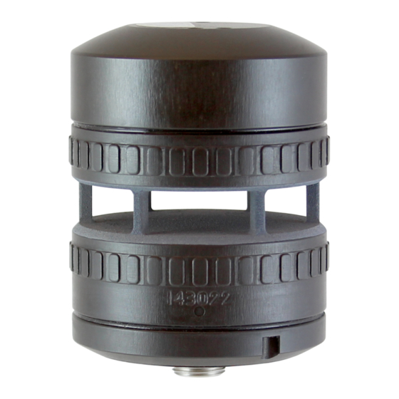
1 INTRODUCTION 1.1 Product Overview The FT742-SM is a solid-state ultrasonic wind sensor, using a patented Acoustic Resonance airflow sensing technique to measure accurately both wind speed and direction. The sensors have been specifically designed to operate in harsh environments including offshore and ice-prone areas. The wind sensor has no moving parts to degrade or wear and is designed for applications requiring high reliability. -
Page 8: Disclaimer
The Purchaser assumes all risks and liability in conjunction with the use of the information given. Any warranty given by FT Technologies in respect of the Equipment is conditional upon the sensor being handled, installed, integrated and operated in accordance within the guidelines given in this manual. -
Page 9: Functional Description
3. See safety instruction requirements (page 5 and 6). 4. The heater set-point temperature can be configured by the user. Modifications to the heater current limit and under-voltage limit are not permitted on the FT742-SM range, for further details contact FT Technologies. -
Page 10: Wind Speed Calibration
(See Sections 7.4.8 and 7.4.9). Figure 2: Examples of FIR Filtering It is recommended to use average readings to reduce the effects of air turbulence. FT742-SM (RS422 & RS485) Sensors – User Manual... -
Page 11: Electronically Offsetting The Wind Direction Datum
Varying fields caused, for example, by ferrous objects passing near the FT742-SM (say by a car or truck) or high current electric circuits will not be corrected. Should the magnetic signature of the host system change significantly (because component parts have been added or removed), then a recalibration may be required. -
Page 12: Overspeed Warning Scheme
FT technical support teams for further information. Caution - Modifications to the heater current limit are not permitted on the FT742-SM. Cables must be suitably rated for the application. Contact FT Technologies for further information. -
Page 13: Mechanical & Electrical Installation
Section 3 Mechanical & Electrical Installation 3 MECHANICAL & ELECTRICAL INSTALLATION The FT742-SM has a surface-mounted design for installation on flat surfaces. The product range is optimised for cost-efficient operation including the use of standard off-the-shelf cables. The sensor uses an 8-way M12 connector. IP66 and IP67 ratings are achieved through the use of a compression fit O-ring seal. - Page 14 Section 3 Mechanical & Electrical Installation FT742-SM (RS422 & RS485) Sensors – User Manual...
- Page 15 Figure 5 displays the location of the O-ring groove (FT O-ring part number FT029, manufacturer part number: 2-127 O-Ring EPDM 70 Shore). One O-ring is supplied with new sensors. The use of lubricant on the O-ring will depend on the material selection. FT742-SM (RS422 & RS485) Sensors – User Manual...
-
Page 16: Connector Details
Figure 6: Sensor Connector Pin The FT742-SM sensor uses a M12 8-way male connector (ERNI Production GmbH, part number 464676). Finished cable assemblies are available off-the-shelf as well as custom manufacture. The FT742-SM can use up to 2A with the heater enabled, it is necessary to confirm all cables used are suitably rated for the operational environment. -
Page 17: Service, Configuration & Testing
If any debris is present this can be removed by gently rinsing the measurement cavity surface with distilled water using a laboratory wash bottle or similar. Please note excess water droplets can be removed by lightly blowing or shaking the sensor. FT742-SM (RS422 & RS485) Sensors – User Manual... -
Page 18: Fault Finding & Troubleshooting
If there are signs of physical damage and/or the sensor is failing to communicate properly, it should be replaced. Sensors may be returned to FT Technologies for further analysis if required (see Section 4.3). Warning – The sensor contains no user serviceable components. Do not attempt disassembly as damage may result and product warranties will be invalidated. -
Page 19: Evaluation
5 Evaluation 5.1 Evaluation Pack To help users carry out a test bench assessment of the FT742-SM sensors, FT Technologies sells two USB test cables allowing connection to the RS422 and RS485 communication variants via USB PC connection. Acu-Test Evaluation Pack – This kit includes a CD with user manuals, the Acu-Vis software installation files and a USB test cable. -
Page 20: Ft058 & Ft059 Evaluation Cables
5.3 FT058 & FT059 Evaluation Cables The FT742-SM can be tested by connecting it to a computer using the relevant FT USB cable and a power supply. Figure 9 shows how the Evaluation Pack can be quickly set up to evaluate the sensor using Acu-Vis. -
Page 21: Software Installation
Figure 10: Acu-Vis Install Files 2. Remove the FT742-SM sensor and USB test cable from their packaging and mate the connectors together 3. Connect the +24 VDC terminal of the power supply (current limit up to 2.5A) to the white wire (Red test plug) and 0V terminal to the brown wire (black test plug). -
Page 22: Sensor Communication
The protocol incorporates checksum validation to ensure the integrity of all data transmissions. In addition to the FT Technologies proprietary protocol the sensor can output the common NMEA 0183 MWV (Wind Speed and Angle) sentence. - Page 23 Round the resistor value up rather than down when selecting form the E24 range. ���� × 754 ����������1 ( ���� ) = − 754 3.125 Supply Voltage Rbias1 (Ω, E24 5%) 2200 5100 6800 FT742-SM (RS422 & RS485) Sensors – User Manual...
- Page 24 Round the resistor up rather than down when selecting form the E24 range. ���� × 754 ����������1 ( ���� ) = − 754 3.125 Supply voltage Rbias1 (Ω, E24 5%) 2200 5100 6800 FT742-SM (RS422 & RS485) Sensors – User Manual...
-
Page 25: Configuring The Sensor
Start of message delimiter Checksum field delimiter Field delimiter Dash <cr> Carriage return End of message delimiter Line feed <lf> <name> Placeholder for data Figure 15: Symbols used in this Handbook FT742-SM (RS422 & RS485) Sensors – User Manual... -
Page 26: Data Transmission
See Section 6.4.5 for information on how to compute the checksum and Section 6.4.6 if checksum message validation is not required. All messages are terminated with a carriage return <cr> and line feed <lf>. FT742-SM (RS422 & RS485) Sensors – User Manual... -
Page 27: Listener And Talker Identifiers
ASCII characters ‘//’ in place of the checksum value. Example: Send a message to set the data output format to Polar using the DFP command (the sensor Listener ID in this example is set to 02) FT742-SM (RS422 & RS485) Sensors – User Manual... - Page 28 A checksum value is always transmitted by the sensor with every outgoing message. However the checksum field can be ignored by the host computer if checksum validation for received messages is not required. FT742-SM (RS422 & RS485) Sensors – User Manual...
-
Page 29: Parameter Settings
To verify that the command has been successfully carried out, an associated QUERY command can be sent after most SET commands (see Section 7.1.2 for the list of parameters which may be queried). FT742-SM (RS422 & RS485) Sensors – User Manual... -
Page 30: Query Commands
Wind speed table record 7.4.22 Table label 7.4.23 7.4.24 Saved User Parameters Matches Saved to Current User Parameters 7.4.25 7.4.26 Wind velocity reading Wind Speed, Direction and Sensor Status 7.4.27 Figure 20: Query Commands FT742-SM (RS422 & RS485) Sensors – User Manual... -
Page 31: User Calibration Table
Read the number of table entries and the table checksum; Read out a selected row of table data, Read out the User Calibration Table label. See Sections 7.4.20 - 7.4.24 for further details. FT742-SM (RS422 & RS485) Sensors – User Manual... -
Page 32: Timing Constraints
A QUERY can then be sent to confirm command has been carried out: $//DF?*//<cr><lf> Then wait 50-100ms for the sensor to send a response: $WI,DF=P*5D<cr><lf> Please note the above example assumes the sensor has a factory default time delay of 50-100ms (DL01). FT742-SM (RS422 & RS485) Sensors – User Manual... -
Page 33: Command Parameters
If you do not know what the current setting of the sensor baud rate is you will need to try each baud rate in turn until you establish communication. FT742-SM (RS422 & RS485) Sensors – User Manual... -
Page 34: Cf: Set Or Query The Wind Compass Settings
Query compass parameters $WI,CF=D,D,005.0,005.0*26<cr><lf> FT742-SM output Example 2 The datum direction of the FT742-SM is pointing 40° to the East – set the declination angle a further 5° East and read the compass heading and declination parameters: Message Comment $01,CF005.0*//<cr><lf>... - Page 35 $01,CFMS*//<cr><lf> Save compass calibration Description Use the CF command to access the compass related features of the FT742-SM. See Sections 2.4 & 2.5 for further details about the compass, declination angle and the calibration procedure. FT742-SM (RS422 & RS485) Sensors – User Manual...
-
Page 36: Cu: Set Or Query The Continuous Update Setting
To achieve this, the CUD (disable continuous update mode) command must be sent within the first four seconds of the power being applied to the sensor. It is possible to modify the four second delay period on the FT742-SM sensor, contact FT Technologies for further information. -
Page 37: Df: Set Or Query The Wind Velocity Data Format
NMEA 0183 Format: The sensor returns the wind angle (0-359 degrees, Relative) and wind speed (m/s, knots or km/h). The sensor TalkerID is always set to WI when NMEA format is selected irrespective of any value that may have been set with the ID command. FT742-SM (RS422 & RS485) Sensors – User Manual... -
Page 38: Dg: Query The Run-Time Counter
Use the DG command to query the number of operational hours that the anemometer has been in use. The Run-Time Counter is incremented on completion of each full hour that the anemometer has been in use. FT742-SM (RS422 & RS485) Sensors – User Manual... -
Page 39: Dl: Set Or Query The Command Delay Interval
For example, if the delay interval is set to 250ms then the sensor will commence outputting the wind velocity data between 250-300ms after receiving a WV query command. If any further commands are sent to the sensor before the delay interval has elapsed they will be discarded. FT742-SM (RS422 & RS485) Sensors – User Manual... -
Page 40: Er: Query Or Reset The Error Report
This report can be sent back to the FT factory for analysis if there are problems with the sensor. Currently the historical error log is only used for factory diagnostic purposes. FT742-SM (RS422 & RS485) Sensors – User Manual... -
Page 41: Fl.1: General Filter Settings
Disable filtering $01,FL?*//<cr><lf> Query filter setting $WI,FL=D*41<cr><lf> Sensor response Description Use the FL command to enable or disable moving average filtering of the wind speed and wind direction readings (see Section 2.3). FT742-SM (RS422 & RS485) Sensors – User Manual... -
Page 42: Fl.2: Set Or Query Filter Lengths
1. So setting a filter to a length of 0001 gives just the current reading (see Section 2.3). The sensor’s internal memory is large enough to retain 64 previous speed and direction readings, allowing for maximum filter length of 6.4 seconds. FT742-SM (RS422 & RS485) Sensors – User Manual... -
Page 43: Fl.3: Set Or Query The Selective Filter
This scheme can be enabled by factory configuration. The filter is turned off by default to match legacy behaviour. Depending on the control system used, this may improve data quality. FT742-SM (RS422 & RS485) Sensors – User Manual... -
Page 44: Ht.1: General Heater Settings
It is also possible to query the duty cycle of the heater, which specifies the percentage of the current being drawn by the heaters. Note: Modifications to the heater current maximum limit are not permitted on the FT742-SM range. Contact FT technical support for further information. -
Page 45: Ht.2: Delay Heater Settings
Use the HT command to set the sensor heater parameters, including setting a delay time which specifies how many seconds will elapse after powering on the sensor before the heater is enabled. FT742-SM (RS422 & RS485) Sensors – User Manual... -
Page 46: Id: Set Or Query The Listener & Talker Identifiers
Note: the ID? command must use the new listener ID otherwise the command will not be recognised. Description Use the ID command to set the listener and talker address identifiers. See Section 6.4.4 for information on listener and talker address identifiers. FT742-SM (RS422 & RS485) Sensors – User Manual... -
Page 47: Mm: Reset Or Query The Min/Max Recorded Wind Speed
The minimum and maximum readings are set to their default values when an MMR, an RS or a DF set command is executed. FT742-SM (RS422 & RS485) Sensors – User Manual... -
Page 48: Os: Overspeed Warning Scheme
Disable the Overspeed Warning scheme. Verify that the command has been accepted. Message Comment $01,OSD*//<cr><lf> Disable the scheme $01,OS?*//<cr><lf> Query Overspeed Warning scheme $WI,OS=D*57<cr><lf> Sensor response Description Use this command to query, enable or disable the Overspeed Warning Scheme (See Section 2.8). FT742-SM (RS422 & RS485) Sensors – User Manual... -
Page 49: Pr: Query The Parameter Report
Use the PR command to generate a sensor report. This report can be sent back to the FT factory for analysis if there are problems with the sensor. Currently the parameter report is only used for factory diagnostic purposes. FT742-SM (RS422 & RS485) Sensors – User Manual... -
Page 50: Rs: Reset The Sensor
To restart the software, but load the saved parameter settings use the RSS command. To restart the software, but load the factory default parameter settings use the RSF command See command US (Section 7.4.25) for a description for setting or querying these Saved Parameters. FT742-SM (RS422 & RS485) Sensors – User Manual... -
Page 51: Sn: Query The Serial Number And Platform Version
The serial number format starts with a 5 digit batch code, followed by a 3 digit number which identifies a sensor within a particular batch. The overall number is the unique serial number identifier for the sensor. FT742-SM (RS422 & RS485) Sensors – User Manual... -
Page 52: Query The Software Version
Software version of the sensor. The spaces are reserved for future use. Examples Example 1 Read the software version number Message Comment $01,SV?*//<cr><lf> Query software version $WI,SV= *00<cr><lf> Sensor response Description The SV command returns the software version of the sensor. FT742-SM (RS422 & RS485) Sensors – User Manual... -
Page 53: Uc.1: General User Calibration Settings
(nn) will be 00 and the saved user calibration table Flash copy checksum (zzzz) will be 5535. When the User Calibration facility is enabled, the uncorrected wind speed indication of the sensor is calibrated according to the stored calibration records, using linear interpolation. FT742-SM (RS422 & RS485) Sensors – User Manual... -
Page 54: Uc.2: Clear User Calibration Table Record
A UCCLEAR is performed before a new user calibration table is loaded (see Section 7.4.22). The user calibration table label is also cleared to 32 ASCII spaces when the UCCLEAR command is sent (see Section 7.4.24). FT742-SM (RS422 & RS485) Sensors – User Manual... -
Page 55: Uc.3: Set User Calibration Table Record
Up to 64 records can be entered sequentially into the sensor’s RAM and verified. Once sufficient records have been loaded, these can be saved to the Flash using the user calibration save command (see Section 7.4.23). FT742-SM (RS422 & RS485) Sensors – User Manual... -
Page 56: Uc.4: Save And Read User Calibration Table
Use the UC?R command to verify the data stored in an individual Flash calibration record. Once the table has been saved into Flash memory, new data and the text string can only be written to it by first clearing the table. FT742-SM (RS422 & RS485) Sensors – User Manual... -
Page 57: Uc.5: Set & Query User Calibration Table Label
The user calibration table label can be cleared by using the UCCLEAR command. (see Section 7.4.21) This resets the label to 32 ASCII spaces. UC?T query command will only return a response after the user calibration table has been initialised. FT742-SM (RS422 & RS485) Sensors – User Manual... -
Page 58: Set Or Query Saved Parameters
The Factory Parameters retain the original default settings and cannot be modified, but can be used to replace the User Parameter, by using the RSF command (see Section 7.4.17) Continued over the page… FT742-SM (RS422 & RS485) Sensors – User Manual... - Page 59 User version becomes corrupt there is always a ‘clean’ back up Saved copy of the parameters that can be used to recover the sensor. FT742-SM (RS422 & RS485) Sensors – User Manual...
-
Page 60: Wv Polar: Query The Wind Velocity Reading
The status is cleared once the WV command is executed, provided that the error condition does not persist. FT742-SM (RS422 & RS485) Sensors – User Manual... -
Page 61: Wv Nmea: Query The Wind Velocity Reading
MWV Wind Speed and Angle sentence. The sensor Talker ID is always set to WI when NMEA format is selected, irrespective of any setting that may have been set with the ID command. End of Manual – Back to Contents FT742-SM (RS422 & RS485) Sensors – User Manual...
Need help?
Do you have a question about the FT742-SM and is the answer not in the manual?
Questions and answers