Table of Contents
Advertisement
Quick Links
FT742-SM – Digital Wind Sensor User Manual
Surface-Mounted - Digital RS422 & RS485 options
FT TECHNOLOGIES LTD.
SUNBURY HOUSE
BROOKLANDS CLOSE
SUNBURY-ON-THAMES
MIDDLESEX TW16 7DX
A4281-3-EN
July 2019
The FT and Acu-Res logos are registered trademarks of FT Technologies Ltd.
Copyright © 2019 FT Technologies Ltd. All rights reserved.
1
FT742-SM (RS422 & RS485) Sensors – User Manual
TEL: +44 (0)20 8943 0801
FAX: +44 (0)20 8943 3283
WEB:
www.fttechnologies.com
E-MAIL: info@fttechnologies.com
Advertisement
Table of Contents

Related Manuals for FT Technologies acures FT742-SM


Summary of Contents for FT Technologies acures FT742-SM
- Page 1 WEB: www.fttechnologies.com SUNBURY-ON-THAMES E-MAIL: info@fttechnologies.com MIDDLESEX TW16 7DX A4281-3-EN July 2019 The FT and Acu-Res logos are registered trademarks of FT Technologies Ltd. Copyright © 2019 FT Technologies Ltd. All rights reserved. FT742-SM (RS422 & RS485) Sensors – User Manual...
-
Page 2: Table Of Contents
Contents Product Symbols ...................... 4 Safety Instructions ....................5 Consignes de sécurité ..................... 6 INTRODUCTION ....................7 Product Overview ........................ 7 Build Versions and Labelling ..................... 7 Scope of Use ........................7 Disclaimer ..........................8 FUNCTIONAL DESCRIPTION ................9 Technical Performance ....................... 9 Wind Speed Calibration .................... - Page 3 SENSOR COMMUNICATION ................30 Introduction ........................30 RS422 & RS485 Protocol ....................30 Configuring the Sensor ..................... 33 Communication ........................33 6.4.1 Conventions used in this manual ..................33 6.4.2 Data Transmission ......................34 6.4.3 Message Format......................34 6.4.4 Listener and Talker Identifiers ..................35 6.4.5 Calculating the Message Checksum ................
-
Page 4: Product Symbols
Cela doit être fait par le should be done by returning the product to retour du produit à FT Technologies FT Technologies or by using an appropriate ou en utilisant une entreprise waste disposal company. This product d'élimination de déchets. Ce produit should not be disposed of in general waste ne doit pas être éliminé... -
Page 5: Safety Instructions
In accordance with the instructions set out in this manual, observing all information, warnings and instructions In accordance with any other instructions or guidance FT Technologies provide • To ensure that the product remains compliant with the electrical safety requirements of the UL / CSA 61010-1 Standards it must be;... -
Page 6: Consignes De Sécurité
Conformément aux instructions figurant dans ce manuel et en observant toutes les informations, avertissements et instructions Conformément à d'autres instructions ou directives que FT Technologies fournit • Pour garantir que le produit reste compatible avec les exigences de sécurité électrique de l'UL/CSA 61010-1 normes, l'équipement doit être :... -
Page 7: Introduction
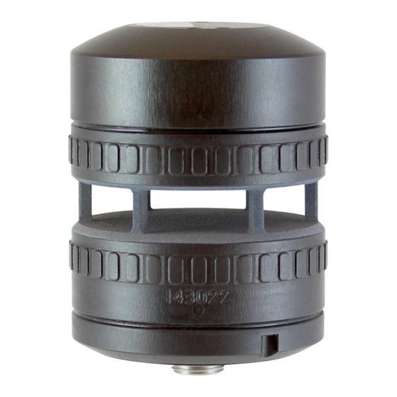
Section 1 Introduction 1 INTRODUCTION 1.1 Product Overview The FT742-SM is a solid-state ultrasonic wind sensor, using a patented Acoustic Resonance airflow sensing technique to measure accurately both wind speed and direction. The sensors have been specifically designed to operate in harsh environments including offshore and ice-prone areas. The wind sensor has no moving parts to degrade or wear and is designed for applications requiring high reliability. -
Page 8: Disclaimer
The Purchaser assumes all risks and liability in conjunction with the use of the information given. Any warranty given by FT Technologies in respect of the Equipment is conditional upon the sensor being handled, installed, integrated and operated in accordance within the guidelines given in this manual. -
Page 9: Functional Description
Section 2 Functional Description 2 FUNCTIONAL DESCRIPTION 2.1 Technical Performance 1 & 2 Sensor Performance Measurement Principle Acoustic Resonance (compensated against variations in temperature, pressure and humidity) Wind Speed Measurement Range 0-75m/s Resolution 0.1m/s Accuracy ±0.3m/s (0-16m/s) ±2% (16m/s-40m/s) ±4% (40m/s-75m/s) Wind Direction Measurement Range 0 to 360°... -
Page 10: Wind Speed Calibration
The sensor’s compact strong monolithic shape is designed to prevent accidental transducer movement or damage. FT Technologies’ calibration procedure and wind tunnels are designed to give a calibration profile that is within the accuracy limits set in the product technical specification (see Section 2.1). -
Page 11: Electronically Offsetting The Wind Direction Datum
Section 2 Functional Description 2.4 Electronically Offsetting the Wind Direction Datum For applications where the compass is not being used, the wind direction datum can be ‘electronically’ rotated using the CF command. The declination angle function normally used in conjunction with the compass function can be used to realign the datum position anywhere in the range 0-359.9°. -
Page 12: Overspeed Warning Scheme
The power supply must be rated to provide the maximum heater power (60W @ 30V and 2A) that the sensor can consume. The heater requires a minimum of 9VDC for operation (contact FT technologies for further details on the minimum heater voltage limit). -
Page 13: Acoustic Temperature
CU data output and WV Query commands. See Sections 7.4.7, 7.4.8 and 7.4.29 for further information. Caution: The acoustic temperature feature requires calibration at FT Technologies. If the sensor has had a software upgrade to 7.5 (or above) then the data will be uncalibrated and may not comply with the official specification. -
Page 14: Mechanical & Electrical Installation
Section 3 Mechanical & Electrical Installation 3 MECHANICAL & ELECTRICAL INSTALLATION The FT742-SM has a surface-mounted design for installation on flat surfaces. The product range is optimised for cost-efficient operation including the use of standard off-the-shelf cables. The sensor uses an 8-way M12 connector. IP66 and IP67 ratings are achieved through the use of a compression fit O-ring seal. - Page 15 Section 3 Mechanical & Electrical Installation FT742-SM (RS422 & RS485) Sensors – User Manual...
- Page 16 Section 3 Mechanical & Electrical Installation Figure 4: Outline Dimensions, Assembly & Wind Direction Reference (Compass Disabled) Figure 5: Sensor Base Dimensions Figure 5 displays the location of the O-ring groove (FT O-ring part number FT029, manufacturer part number: 2-127 O-Ring EPDM 70 Shore). One O-ring is supplied with new sensors. The use of lubricant on the O-ring will depend on the material selection.
-
Page 17: Connector Details
Orange The FT009 cable includes shielding *Caution: Wire colours apply only to FT supplied FT009 cables. Other cables may use different colour schemes, contact FT technologies for further information. Figure 6: Sensor Connector Pin The FT742-SM sensor uses a M12 8-way male connector (ERNI Production GmbH, part number 464676). - Page 18 See the PM wind sensor User Manual for more details on this or contact FT Technologies for more information. Advanced surge and lightning protection typically requires a grounded lightning mast, SPDs, grounded metallic conduit and 360°-terminated EMC cable glands.
-
Page 19: Service, Configuration & Testing
Section 4 Service, Configuration & Testing 4 SERVICE, CONFIGURATION & TESTING 4.1 Inspection The following checks are required to identify any signs of corrosion or damage on the sensor which may hinder its performance. It is recommended that these checks be carried out annually. Mechanical damage: Check the sensor body for signs of damage, paying particular attention to the seals. -
Page 20: Fault Finding & Troubleshooting
Please contact FT Technologies for further information and advice if required. 4.3 Returns If a sensor appears to be faulty, compile a detailed fault description for each sensor, then contact FT Technologies to request a Returns Materials Authorisation (RMA) form. Please complete the form and return as instructed. -
Page 21: Acu-Test Evaluation Kit
Acu-Vis 2.0 software will work on a computer running Microsoft Windows 7, 8, 8.1 and 10. Note: RS485 half-duplex sensors running in Continuous Update (CU) mode can be difficult to communicate with due to the limitations of half-duplex topology. Contact FT Technologies for assistance or disable CU mode using Acu-Vis 2.0 Caution: Live connection/disconnection of the power and/or sensors during live operation, or miswiring of the power leads could damage the equipment and is not covered by FT’s standard warranty terms... -
Page 22: Software Installation
7. Once the above sequence is complete, wait approximately 5 seconds and then run Acu-Vis 2.0 by selecting the shortcut icon on the desktop or from the start menu in the FT Technologies folder. Figure 11: Acu-Vis 2.0 Windows Launch Icon 8. -
Page 23: Acu-Vis 2.0 Software Operation
Figure 12: Acu-Vis 2.0 Connect Display 1. The Acu-Test cable serial number 2. About Window: FT Technologies contact information and software build versions Language selection options: English, French, Chinese, Spanish, Japanese and Korean FT742-SM (RS422 & RS485) Sensors – User Manual... - Page 24 Section 5 Acu-Test Evaluation Kit The dials show the real-time wind speed and direction. The temperature gauge on the right-hand side shows the Heater Setpoint, Internal Temperature and the ‘Acoustic Temperature’ ambient air reading. Note: Acoustic Temperature data requires software V7.5+ and an FT temperature calibration Figure 13: Acu-Vis 2.0 Live Display The program shows various configuration settings, including the software version and serial number.
- Page 25 Technologies support teams • The ‘Unlock Feature’ button is used to unlock advanced features in Acu-Vis 2.0, including the ‘Commands’ and the ‘User Calibration Table’ tabs. Contact FT Technologies for further details FT742-SM (RS422 & RS485) Sensors – User Manual...
- Page 26 Section 5 Acu-Test Evaluation Kit Commands Tab The Command tab allows the user to view and send various software commands: Figure 15: Command Line Terminal Display • Search for commands (for example: BR) or select them from the ‘Sensor Host Command’ menu. Selecting a query will add the command to the ‘Execute Command’...
- Page 27 Section 5 Acu-Test Evaluation Kit UCT (‘User Calibration Table’) Tab The UCT window provides the user with a simple method of changing the calibration performance of the sensor. Refer to the UCT commands detailed in the user manual for further information. Acu-Vis 2.0 will download any existing UCT settings and display them on the table and graph.
-
Page 28: Command Line Terminal Programs (Including Teraterm)
Section 5 Acu-Test Evaluation Kit 5.4 Command Line Terminal Programs (Including TeraTerm) The Acu-Test cables can be used to communicate via command line terminal programs, including Hyperterminal and TeraTerm. This provides a simple user interface without creating an RS485HD or RS422 network. To begin a TeraTerm connection click ‘New Connection’... - Page 29 Section 5 Acu-Test Evaluation Kit Figure 18: Modifying Terminal Settings in TeraTerm TeraTerm defaults to a baud rate of 9600 - it may be necessary to configure this via the Setup menu (Setup > Serial Port). With connection enabled with the settings configured as described above, send commands to the sensor to confirm successful connection.
-
Page 30: Sensor Communication
The protocol incorporates checksum validation to ensure the integrity of all data transmissions. In addition to the FT Technologies proprietary protocol the sensor can output the common NMEA 0183 MWV (Wind Speed and Angle) sentence. - Page 31 Section 6 Sensor Communication Figure 20: RS-485HD Connection Diagram for 2 Wind Sensors Notes: 1. Data lines A & B should be twisted-pair type (characteristic impedance 120Ω). The cable should incorporate overall screening braid which should be connected to the chassis at each circuit node. 2.
- Page 32 Section 6 Sensor Communication Figure 21: RS-422 Connection Diagram Notes: 1. Data lines A & B should be twisted-pair type (characteristic impedance 120Ω). The cable should incorporate overall screening braid which should be connected to chassis at each circuit node. 2.
-
Page 33: Configuring The Sensor
Section 6 Sensor Communication 6.3 Configuring the Sensor All user parameter settings are stored in non-volatile memory and are retained when the sensor is switched off. When the sensor is next switched on (or a user reset command is sent) the sensor will revert to these settings. The sensor can therefore be configured prior to final installation if required. -
Page 34: Data Transmission
Section 6 Sensor Communication 6.4.2 Data Transmission Data is transmitted and received via an asynchronous serial communication interface using ASCII characters. The interface operates with the following parameters: Parameter Setting 1200, 2400, 4800, 9600 (factory default), 19200, 38400 Baud Rate Can be programmed at factory to customer requirement Data Bits Start Bits... -
Page 35: Listener And Talker Identifiers
Section 6 Sensor Communication 6.4.4 Listener and Talker Identifiers The sensor is assigned with both a Listener and Talker identifier address that allows an individual sensor to be uniquely identified in a system comprising more than one sensor. Whenever a message is sent to the sensor, the identifier field of the message (the 2 characters immediately following the ‘$’... - Page 36 Section 6 Sensor Communication With a checksum (sensor checksum validation automatically enabled): $02DFP*50<cr><lf> Without a checksum (sensor checksum validation automatically disabled): $02DFP*//<cr><lf> A checksum value is always transmitted by the sensor with every outgoing message. However the checksum field can be ignored by the host computer if checksum validation for received messages is not required. FT742-SM (RS422 &...
-
Page 37: Parameter Settings
Section 7 Parameter Settings 7 PARAMETER SETTINGS 7.1 Command Types 7.1.1 Set Commands Figure 26 lists the commands that may be sent to the sensor from the host computer that are used to SET configuration options for the wind sensor. Command Mnemonic Configuration Options... -
Page 38: Query Commands
Section 7 Parameter Settings 7.1.2 Query Commands Figure 27 lists the commands that may be sent to the sensor from the host computer that are used to QUERY the wind sensor’s latest readings or configuration. Command Mnemonic Sensor Data Returned Section Normal Anemometer Mount... -
Page 39: User Calibration Table
Section 7 Parameter Settings 7.2 User Calibration Table The User Calibration Table includes up to 64 user programmable records. Each record comprises a pair of values representing the corrected speed (wind tunnel speed) and the corresponding uncorrected wind sensor speed. In addition to the calibration table, there is provision for a user-defined text string of up to 32 characters which is stored together with the table. -
Page 40: Timing Constraints
Section 7 Parameter Settings 7.3 Timing Constraints When a valid command is received by the sensor input buffer, there will be a time delay whist the command is being processed. The actual command latency depends on exactly when the last character of the command is received within the sensor internal processing cycle. -
Page 41: Command Parameters
Section 7 Parameter Settings 7.4 Command Parameters Each command, and its usage, is described in the following Sections. All examples, other than where stated, assume that the sensor Listener ID is set to 01, and the sensor TalkerID is set to WI, (Weather Instrument). 7.4.1 AM: Set or Query Anemometer Mount Orientation Command... -
Page 42: At.1: Query The Acoustic Temperature
CU & WV output data. A new DF command option (see Section 7.4.8) controls this mode. Caution: The acoustic temperature feature requires calibration at FT Technologies. If the sensor has had a software upgrade to V7.5 (or above) then the data will be uncalibrated and may not comply with the official specification. -
Page 43: At.2: Set Or Query The Acoustic Temperature Units
Section 7 Parameter Settings 7.4.3 AT.2: Set or Query the Acoustic Temperature Units Command AT (units) Parameter $<listenerID>,ATU<units>*<checksum><cr><lf> Command SET Sensor: $aa,ATUc*hh<cr><lf> Syntax $aa,AT?U*hh<cr><lf> QUERY Sensor: $<talkerID>,AT=<units>*<checksum><cr><lf> Sensor output: $aa,AT=c*hh<cr><lf> Parameters <units> The Acoustic Temperature is to be output in degrees Celsius The Acoustic Temperature is to be output in degrees Fahrenheit The Acoustic Temperature is to be output in Kelvin Examples... -
Page 44: At.3 Set Or Query The Acoustic Temperature Filter Length
Section 7 Parameter Settings 7.4.4 AT.3 Set or Query the Acoustic Temperature Filter Length Command AT (filter length) Parameter $<listenerID>,ATF<filter length>*<checksum><cr><lf> Command SET Sensor: $aa,ATFxxc*hh<cr><lf> Syntax $<listenerID>,AT?F*<checksum><cr><lf> QUERY Sensor: $aa,AT?F*hh<cr><lf> $<talkerID>,AT=<filter length>*<checksum><cr><lf> Sensor output: $aa,AT=xxc*hh<cr><lf> Parameters <filter length> 00S to 50S, Time constant of the acoustic temperature filter in seconds (S) or minutes 01M to 10M (M). -
Page 45: Br: Set Or Query The Serial Interface Baud Rate
Section 7 Parameter Settings 7.4.5 BR: Set or Query the Serial Interface Baud Rate Command Parameter $<listenerID>,BR<baudrate>*<checksum><cr><lf> Command SET Sensor: $aa,BRx*hh<cr><lf> Syntax $<listenerID>,BR?*<checksum><cr><lf> QUERY Sensor: $aa,BR?*hh<cr><lf> $<talkerID>,BR=<baudrate>*<checksum><cr><lf> Sensor Output: $aa,BR=x*hh<cr><lf> Parameters <baudrate> Set the baud rate to 38400 baud Set the baud rate to 19200 baud Set the baud rate to 9600 baud (Factory Default Setting) Set the baud rate to 4800 baud Set the baud rate to 2400 baud... -
Page 46: Cf: Set Or Query The Wind Compass Settings
Section 7 Parameter Settings 7.4.6 CF: Set or Query the Wind Compass Settings Command CF(heading) Parameter $<listenerID>,CF<mode>*<checksum><cr><lf> Command $aa,CFc*hh<cr><lf> Syntax SET Sensor: $<listenerID>,CF<heading>*<checksum><cr><lf> $aa,CFxxx.x*hh<cr><lf> $<listenerID>,CF?*<checksum><cr><lf> QUERY Sensor: $aa,CF?*hh<cr><lf> $<talkerID>,CF=<mode>,<status>,<heading>,<dec>* <checksum><cr><lf> FT742-SM output: $aa,CF=c,c,xxx.x,xxx.x*hh<cr><lf> Parameters <heading> 000.0 to 359.9 Compass heading in degrees <mode>... - Page 47 Section 7 Parameter Settings Example 4 Enable the calibration procedure and save the results $01,CFC*//<cr><lf> Enable compass calibration $01,CFE*//<cr><lf> Disable compass calibration $01,CFMS*//<cr><lf> Save compass calibration Description Use the CF command to access the compass related features of the FT742-SM. See Sections 2.4 &...
-
Page 48: Cu: Set Or Query The Continuous Update Setting
It is possible to modify the four second delay period on the FT742-SM sensor, contact FT Technologies for further information. Note: CU mode operation typically uses RS422 communication. For CU mode operation in RS485, software version 7.4 and above will be required. - Page 49 Section 7 Parameter Settings WARNING: Do not use the continuous update mode if there are other talkers connected to the data bus. Only one active talker is allowed on the data bus at any one time otherwise bus contention will occur FT742-SM (RS422 &...
-
Page 50: Df: Set Or Query The Wind Velocity Data Format
Section 7 Parameter Settings 7.4.8 DF: Set or Query the Wind Velocity Data Format Command Parameter $<listenerID>,DF<format>*<checksum><cr><lf> Command $aa,DFc*hh<cr><lf> or Syntax SET Sensor: $aa,DFcc*hh<cr><lf> $<listenerID>,DF?*<checksum><cr><lf> QUERY Sensor: $aa,DF?*hh<cr><lf> $<talkerID>,DF=<format>*<checksum><cr><lf> Sensor output: $aa,DF=c*hh<cr><lf> Parameters <format> Set the data format to Polar (wind speed and direction) (Factory Default Setting) Set the data format to NMEA 0183 with wind speed in m/s Set the data format to NMEA 0183 with wind speed in knots... - Page 51 Section 7 Parameter Settings Description Use the DF command to set the required format of the wind velocity readings. See command WV (Sections 7.4.29 and 7.4.30) for a description of the sensor output for each of the format types. When a DF Set command is sent to the sensor, a reset of the minimum and maximum readings to their default values is automatically performed.
-
Page 52: Dg: Query The Run-Time Counter
Section 7 Parameter Settings 7.4.9 DG: Query the Run-time Counter Command Parameter Command SET Sensor: Syntax $<listenerID>,DG?T*<checksum><cr><lf> QUERY Sensor: $aa,DG?T*hh<cr><lf> $<talkerID>,DG=<counter>*<checksum><cr><lf> Sensor output: $aa,DG=xxxxxx*hh<cr><lf> Parameters <counter> 000000 to Holds the number of hours that the anemometer has been in 999999 operation during its lifetime. -
Page 53: Dl: Set Or Query The Command Delay Interval
Section 7 Parameter Settings 7.4.10 DL: Set or Query the Command Delay Interval Command Parameter $<listenerID>,DL<delay>*<checksum><cr><lf> Command SET Sensor: $aa,DLxx*hh<cr><lf> Syntax $<listenerID>,DL?*<checksum><cr><lf> QUERY Sensor: $aa,DL?*hh<cr><lf> $<talkerID>,DL=<delay>*<checksum><cr><lf> Sensor output: $aa,DL=xx*hh<cr><lf> Parameters <delay> 00 to 20 (delay interval, in 50ms increments) (Factory Default Setting = 01) Examples Example 1 Set the command delay interval to 250ms and verify the new setting. -
Page 54: Er: Query Or Reset The Error Report
Section 7 Parameter Settings 7.4.11 ER: Query or Reset the Error Report Command Parameter $<listenerID>,ER<reset>*<checksum><cr><lf> Command SET Sensor: $aa,ERc*hh<cr><lf> Syntax $<listenerID>,ER?*<checksum><cr><lf> QUERY Sensor: $aa,ER?*hh<cr><lf> $<talkerID>,ER=<error report>*<checksum><cr><lf> Sensor output: $aa,ER=xxxxxxxxxxxxxxx*hh<cr><lf> Parameters <reset> Resets the historical log section of the error report to all 0’s <error report>... -
Page 55: Fl.1: Set Or Query General Filter Settings
Section 7 Parameter Settings 7.4.12 FL.1: Set or Query General Filter Settings Command FL (enable/ disable) Parameter $<listenerID>,FL<filter>*<checksum><cr><lf> Command SET Sensor: $aa,FLc*hh<cr><lf> Syntax $<listenerID>,FL?*<checksum><cr><lf> QUERY Sensor: $aa,FL?*hh<cr><lf> $<talkerID>,FL=<filter>*<checksum><cr><lf> Sensor output: $aa,FL=c*hh<cr><lf> Parameters <filter> Filter enabled (Factory Default Setting) Filter disabled Examples Example 1 Enable the filter. -
Page 56: Fl.2: Set Or Query Filter Lengths
Section 7 Parameter Settings 7.4.13 FL.2: Set or Query Filter Lengths Command FL (lengths) Parameter $<listenerID>,FLL<speedLen>,<dirLen>*<checksum><cr> Command <lf> Syntax SET Sensor: $aa,FLLxxxx,xxxx*hh<cr><lf> $<listenerID>,FL?L*<checksum><cr><lf> QUERY Sensor: $aa,FL?L*hh<cr><lf> $<talkerID>,FL=<speedLen>,<dirLen>*<checksum><cr><l f> Sensor output: $aa,FL=xxxx,xxxx*hh<cr><lf> Parameters <speedLen> 0001 to 0064 Sample size of the wind speed filter. Number of previous readings used to calculate the latest wind speed reading, 0001 is equivalent to disabling the filter... -
Page 57: Fl.3: Set Or Query The Selective Filter
Section 7 Parameter Settings 7.4.14 FL.3: Set or Query the Selective Filter Command FL (selective filter) Parameter $<listenerID>,FLS<FilterStatus><period>*<checksum><cr Command ><lf> Syntax SET Sensor: $aa,FLScxxx*hh<cr><lf> $<listenerID>,FL?S*<checksum><cr><lf> QUERY Sensor: $aa,FL?S*hh<cr><lf> $<talkerID>,FL=<FilterStatus>,<period>*<checksum><cr> <lf> Sensor output: $aa,FL=c,xxx*hh<cr><lf> Parameters <FilterStatus> Enabled Disabled <Period> 000 to 255 Length of validity period (in increments of 0.1 seconds): 000 A single error will trigger the error flag 001 2 consecutive errors will trigger the error flag (0.2 seconds) -
Page 58: Ht.1: Set Or Query General Heater Settings
Section 7 Parameter Settings 7.4.15 HT.1: Set or Query General Heater Settings Command HT (enable/ disable) Parameter $<listenerID>,HT<tsp>*<checksum><cr><lf> Command SET Sensor: $aa,HTxx*hh<cr><lf> Syntax $<listenerID>,HT?*<checksum><cr><lf> QUERY Sensor: $aa,HT?*hh<cr><lf> $<talkerID>,HT=<tsp>,<%>,<temp>*<checksum><cr><lf> Sensor output: $aa,HT=xx,xx, xx*hh<cr><lf> Parameters <tsp> 00-55 Heater control circuit set point temperature (degrees Celsius) Disables the heater (factory default setting) <%>... -
Page 59: Ht.2: Set Or Query Delay Heater Settings
Section 7 Parameter Settings 7.4.16 HT.2: Set or Query Delay Heater Settings Command HT (delay) Parameter $<listenerID>,HTD<delay>*<checksum><cr><lf> Command SET Sensor: $aa,HTDxxx*hh<cr><lf> Syntax $<listenerID>,HT?D*<checksum><cr><lf> QUERY Sensor: $aa,HT?D*hh<cr><lf> $<talkerID>,HT=<delay>*<checksum><cr><lf> Sensor output: $aa,HT=xxx*hh<cr><lf> Parameters <delay> 004 to 999 Heater Delay in seconds. This is the period after sensor power on before the heater will be enabled. -
Page 60: Id: Set Or Query The Listener & Talker Identifiers
Section 7 Parameter Settings 7.4.17 ID: Set or Query the Listener & Talker Identifiers Command Parameter $<listenerID>,ID<RxID><TxID>*<checksum><cr><lf> Command SET Sensor: $aa,ID=cccc*hh<cr><lf> Syntax $<listenerID>,ID?*<checksum><cr><lf> QUERY Sensor: $aa,ID?*hh<cr><lf> $<talkerID>,ID=<RxID><TxID>*<checksum><cr><lf> Sensor output: $aa,ID=cccc*hh<cr><lf> Parameters <RxID> 00 to ZZ The sensor 2 digit listener address identifier (Factory Default RxID = 01) <TxID>... -
Page 61: Mm: Reset Or Query The Min/Max Recorded Wind Speed
Section 7 Parameter Settings 7.4.18 MM: Reset or Query the Min/Max Recorded Wind Speed Command Parameter $<listenerID>,MM<setting>*<checksum><cr><lf> Command SET Sensor: $aa,MMc*hh<cr><lf> Syntax $<listenerID>,MM?*<checksum><cr><lf> QUERY Sensor: $aa,MM?*hh<cr><lf> $<talkerID>,MM=<MinSpeed>,<MaxSpeed>*<checksum><cr> <lf> Sensor output: $aa,MM=xxx.x,xxx.x*hh<cr><lf> Parameters <setting> Resets the min/max readings to their default (<MinSpeed> to 999.9 and <MaxSpeed>... -
Page 62: Os: Set Or Query Overspeed Warning Scheme
Section 7 Parameter Settings 7.4.19 OS: Set or Query Overspeed Warning Scheme Command Parameter $<listenderID>,OS<mode>*<checksum><cr><lf> Command SET Sensor: $aa,OSm*hh<cr><lf> Syntax $<listenerID>,OS?*<checksum><cr><lf> QUERY Sensor: $aa,OS?*hh<cr><lf> $<talkerID>,OS=<mode>*<checksum><cr><lf> Sensor output: $aa,OS=m*hh Parameters <Mode> Overspeed Warning Disabled Overspeed Warning Enabled Examples Example 1 Enable the Overspeed Warning scheme. Verify that the command has been accepted. Message Comment $01,OSE*//<cr><lf>... -
Page 63: Rs: Reset The Sensor
Section 7 Parameter Settings 7.4.20 RS: Reset the Sensor Command Parameter $<listenerID>,RS<mode>*<checksum><cr><lf> Command SET Sensor: $aa,RSc*hh<cr><lf> Syntax QUERY Sensor: None Sensor output: Parameters <mode> Reset the sensor, loading the factory default settings Reset the sensor, loading saved parameters settings Reset the sensor, reloading the user parameter settings Examples Example 1 Reset the sensor, reloading the last parameter settings... -
Page 64: Sn: Query The Serial Number And Platform Version
Section 7 Parameter Settings 7.4.21 SN: Query the Serial Number and Platform Version Command Parameter Command SET Sensor: Syntax $<listenerID>,SN?*<checksum><cr><lf> QUERY Sensor: $aa,SN?*hh<cr><lf> $<talkerID>,SN=<SerialNumber>,<PlatformVersion>*<ch ecksum><cr><lf> Sensor Output: $aa,SN=xxxxx-xxx,xxsss*hh<cr><lf> Parameters <SerialNumber> 00000-000 to Unique serial number of the sensor 99999-999 <PlatformVersion> 00-99 Platform version (issue) of the sensor design. -
Page 65: Query The Software Version
Section 7 Parameter Settings 7.4.22 SV: Query the Software Version Command Parameter Command SET Sensor: Syntax $<listenerID>,SV?*<checksum><cr><lf> QUERY Sensor: $aa,SV?*hh<cr><lf> $<talkerID>,SV=<SoftwareVersion>*<checksum><cr><lf> $aa,SV=sssx.xss*hh<cr><lf> Sensor Output: $<talkerID>,SV=<SoftwareVersion>*<checksum><cr><lf> $aa,SV=sssx.x.x*hh<cr><lf> Parameters <SoftwareVersion> 1.0 to 9.9 Software version of the sensor. 1.0.0 to 9.9.9 Examples Example 1 Read the software version number Message... -
Page 66: Uc.1: General User Calibration Settings
Section 7 Parameter Settings 7.4.23 UC.1: General User Calibration Settings Command UC (enable/ disable) Parameter $<listenerID>,UC<table>*<checksum><cr><lf> Command SET Sensor: $aa,UCx*hh<cr><lf> Syntax $<listenerID>,UC?*<checksum><cr><lf> QUERY Sensor: $aa,UC?*hh<cr><lf> $<talkerID>,UC=<entries>,<table>,<UCRAMChecksum >, <UCFlashChecksum>*<checksum><cr><lf> Sensor output: $aa,UC=nn,x,yyyy,zzzz*hh<cr><lf> <table> Parameters User Calibration Table enabled User Calibration Table disabled (Factory Default Setting) <entries>... -
Page 67: Uc.2: Clear User Calibration Table Record
Section 7 Parameter Settings 7.4.24 UC.2: Clear User Calibration Table Record Command UC (Erase table) Parameter $<listenerID>,UC<erase>*<checksum><cr><lf> Command SET Sensor: $aa,UCCLEAR*hh<cr><lf> Syntax <erase> Parameters CLEAR Erases both Flash and RAM copies of user calibration table Examples Example 1 Erase the user calibration tables and verify Message Comment $01,UCCLEAR*62<cr><lf>... -
Page 68: Uc.3: Set User Calibration Table Record
Section 7 Parameter Settings 7.4.25 UC.3: Set User Calibration Table Record Command UC (set & verify record) Parameter $<listenerID>,UCW<Cspeed>,<Uspeed>*<checksum><c Command SET Sensor Calibration r><lf> Syntax Record: $aa,UCWxx.xx,yy.yy*hh<cr><lf> $<listenerID>,UC?W*<checksum><cr><lf> Verify Last Record: $aa,UC?W*hh<cr><lf> $<talkerID>,UC=<error code>*<checksum><cr><lf> Sensor output: $aa,UC=n*hh<cr><lf> <Cspeed> Parameters xx.xx Corrected speed <Uspeed>... -
Page 69: Uc.4: Save And Read User Calibration Table
Section 7 Parameter Settings 7.4.26 UC.4: Save and Read User Calibration Table Command UC (save and read) Parameter $<listenerID>,UCS*<checksum><cr><lf> Command Save Sensor Calibration $aa,UCS*hh<cr><lf> Syntax Record: $<listenerID>,UC?R<row>*<checksum><cr><lf> QUERY Saved Sensor $aa,UC?Rnn*hh<cr><lf> Calibration Record: $<talkerID>,UC=<row>,<Cspeed>,<Uspeed>*<checksu m><cr><lf> Sensor output: $aa,UC=nn,xx.xx,yy.yy*<cr><lf> <row> Parameters 01 –... -
Page 70: Uc.5: Set & Query User Calibration Table Label
Section 7 Parameter Settings 7.4.27 UC.5: Set & Query User Calibration Table Label Command UC (label) Parameter $<listenerID>,UCT<text Command string>*<checksum><cr><lf> Syntax SET Sensor label: $aa,UCTxxxxxxxxxxxxxxxxxxxxxxxxxxxxxxxx*hh<cr>< lf> $<listenerID>,UC?T*<checksum><cr><lf> QUERY Sensor label: $aa,UC?T*hh<cr><lf> $<talkerID>,UC=<label32>*<checksum><cr><lf> Sensor output: $aa,UC=xxxxxxxxxxxxxxxxxxxxxxxxxxxxxxxx*hh<cr>< lf> <text string> Parameters xxxxxxxxxxxxxxxxxx Up to 32 upper or lower case alphanumeric ASCII characters xxxxxxxxxxxxxx (can also include ASCII space, underscore and hyphen... -
Page 71: Set Or Query Saved Parameters
Section 7 Parameter Settings 7.4.28 US: Set or Query Saved Parameters Command Parameter $<listenerID>,US<setting>*<checksum><cr><lf> Command SET Sensor: $aa,USS*hh<cr><lf> Syntax $<listenerID>,US?*<checksum><cr><lf> QUERY Sensor: $aa,US?*hh<cr><lf> $<talkerID>,US=<match>*<checksum><cr><lf> Sensor output: $aa,US=c*hh<cr><lf> Parameters <setting> Copies the User Parameters and saves them as the Saved Parameters. <match>... - Page 72 Section 7 Parameter Settings Description continued The Saved Parameters are created by means of the USS command. This command copies the User Parameters and saves them into a separate area in Flash reserved for the Saved Parameters. The query US command compares item by item the Saved Parameters against the User Parameters and reports any discrepancy;...
-
Page 73: Wv Polar: Query The Wind Velocity Reading
Section 7 Parameter Settings 7.4.29 WV Polar: Query the Wind Velocity Reading Command WV (Polar) Parameter Command SET Sensor: Syntax $<listenerID>,WV?*<checksum><cr><lf> QUERY Sensor: $aa,WV?*hh<cr><lf> $<talkerID>,WVP=<speed>,<angle>,<status>*<checksum> <cr><lf> $aa,WVP=xxx.x,yyy,z*hh<cr><lf> For DFC Mode: Sensor output: $<talkerID>,WVP=<speed>,<angle>,<status>,<temperatu re>,<temp.units>,<temp.status>*<checksum><cr><lf> $aa,WVP=www.w,xxx,y,zzzz.z,a,b*hh<cr><lf> Parameters <speed> 000.0 to 075.0 Measured wind speed in metres per second <angle>... - Page 74 Section 7 Parameter Settings Description The WV command returns the wind velocity value in the currently selected format. Polar, NMEA 0183 and Combined (Polar Wind & Temperature) data formats are available. Use the DF command (Section 7.4.8) to select the output format. Polar Format: The sensor returns the magnitude of the wind speed (m/s) and the wind direction (0-359°).
-
Page 75: Wv Nmea: Query The Wind Velocity Reading
Section 7 Parameter Settings 7.4.30 WV NMEA: Query the Wind Velocity Reading Command WV (NMEA) Parameter SET Sensor: $<listenerID>,WV?*<checksum><cr><lf> Command QUERY Sensor: $aa,WV?*hh<cr><lf> Syntax $WIMWV,<angle>,<reference,<speed>,<units>,<status>* <checksum><cr><lf> Sensor output: $WIMWV,xxx,R,xxx.x,c,A*hh<cr><lf> <angle> 000 to 359 Measured wind direction in degrees relative to sensor datum <speed>...
Need help?
Do you have a question about the acures FT742-SM and is the answer not in the manual?
Questions and answers