Table of Contents
Advertisement
Quick Links
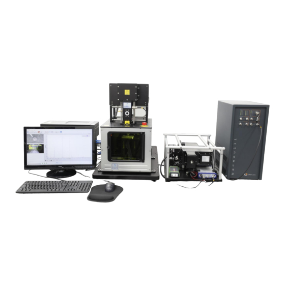
Modular
Laser-Induced Breakdown Spectroscopy (LIBS)
System
Double-pulse, dual wavelength laser (1064 & 266 nm)
High-resolution, broad-band (190 – 1100 nm) echelle spectrograph
User's Manual for Example Configuration 2
June 2022
Applied Photonics Ltd
Unit 8 Carleton Business Park, Skipton, North Yorkshire BD23 2DE, United Kingdom
Tel +44 (0) 1756 708900 Fax +44 (0) 1756 708909 Web: www.appliedphotonics.co.uk
© 1998 - 2022 Applied Photonics Ltd
Advertisement
Table of Contents

Related Manuals for Applied Photophysics LIBS-6


Summary of Contents for Applied Photophysics LIBS-6
- Page 1 Modular Laser-Induced Breakdown Spectroscopy (LIBS) System Double-pulse, dual wavelength laser (1064 & 266 nm) High-resolution, broad-band (190 – 1100 nm) echelle spectrograph User’s Manual for Example Configuration 2 June 2022 Applied Photonics Ltd Unit 8 Carleton Business Park, Skipton, North Yorkshire BD23 2DE, United Kingdom Tel +44 (0) 1756 708900 Fax +44 (0) 1756 708909 Web: www.appliedphotonics.co.uk ©...
-
Page 2: Table Of Contents
Note on the laser safety window material used in the modular sample chambers Electrical General description Overview LIBS-6 module Right-angle mirror modules Adaptor Platforms Litron Bernoulli double-pulse, dual wavelength (1064 & 266 nm) laser EMU-120/65 echelle spectrograph with EMCCD camera... -
Page 3: Introduction
OEMs. Essentially a “LIBS system building block”, the LIBS-6 and LIBS-8 modules may be used together with a variety of Q-switched Nd:YAG lasers and optical spectrometers to form a customised, modular LIBS system tailored to suit the requirements of a specific application or experimental research project. - Page 4 User’s Manual. Interlock Interface Unit Removal of the sample chamber from the LIBS-6 module, or disconnection of the Interlock In/Out lead, will also activate the interlock (ie. prevent activation of the laser). The Interlock Interface Unit is equipped with an Interlock Override facility (a keyswitch) which allows the interlock to be disabled so that the LIBS system may be used without a sample chamber (ie.
- Page 5 “active” unless the laser power supply is deactivated. • NOTE that the transparent acrylic nozzle aperture of the LIBS-6 module does not provide any protection to the user against exposure to direct or scattered laser radiation. The function of the nozzle aperture is described later in this User’s Manual.
-
Page 6: Note On The Laser Safety Window Material Used In The Modular Sample Chambers
(i.e. typically less than 300 mJ with a 5 - 10 ns pulse length). Note that the protective windows are NOT suitable for use with a 532 nm laser. Given that the LIBS-6 (and LIBS-... -
Page 7: Electrical
Electrical The LIBS-6 integrated LIBS module, the XYZ-750 sample chamber and the Raptor Photonics EMCCD camera contain electrical circuits operating at 12 VDC at a maximum current of 2.5 Amps. Accordingly, they pose no electric shock risk. The laser head and associated power supply, however, contain electrical circuits operating at potentially lethal voltage and current levels. -
Page 8: General Description
LIBS-6 modules The NIM LIBS system is supplied with two LIBS-6 modules – one for 1064 nm laser configuration and one for 266 nm laser configuration. Further details on how to use these components are provided later in this User’s Manual. The main components of the LIBS-6 integrated LIBS module are illustrated in the following figures. - Page 9 High- Laser Laser intensity LED warning interlock dimmer light connection control Electrical connection (to sample chamber) Electronics enclosure Optics Lock Camera array Front Transparent screw housing bulkhead nozzle aperture Cut-away to allow adjustment of laser focus Laser beam tube Beam Fibre-optic expander cable...
- Page 10 Gas purge outlet Four high-brightness white LED lights (optional feature) Front view of LIBS-6 module showing plasma light collection lens array, CMOS camera, LED lights, laser aperture and gas purge outlet © 1998 - 2022 Applied Photonics Ltd Page 10 of 42...
- Page 11 100 mm from the aperture of the beam expander. The optical design is specific to the make and model of laser which the LIBS-6 or LIBS-8 module is to be used with – this is specified at the time of ordering of the LIBS module.
-
Page 12: Right-Angle Mirror Modules
Internal view of Mirror Module showing laser beam path The Mirror Module provides precise alignment of the laser beam for the LIBS-6 module which is attached to the output side of the mirror module. Optical alignment is carried out at APL during final assembly of the LIBS equipment and so there should be no need for the user to adjust the internal mirror assembly. -
Page 13: Litron Bernoulli Double-Pulse, Dual Wavelength (1064 & 266 Nm) Laser
Litron Bernoulli double-pulse, dual wavelength (1064 & 266 nm) laser The Bernoulli laser is essentially two laser heads combined into one unit. The laser may be operated in single pulse or double pulse mode. Control of the laser including choosing single pulse or double pulse output is controlled via the LIBSoft software. -
Page 14: Emu-120/65 Echelle Spectrograph With Emccd Camera
EMU-120/65 echelle spectrograph with EMCCD camera The product datasheets for the EMU-120/65 spectrograph (Catalina Scientific, AZ, USA) and the Falcon Blue EMCCD camera (Raptor Photonics, UK) are appended to this User’s Manual. APL supplies the EMU spectrograph with a mounting platform equipped with vibration isolation mounts and a removable protective cage which surrounds the instrument, as illustrated below. -
Page 15: Xyz-750 Computer-Controlled Sample Chamber
XYZ-750 computer-controlled sample chamber The XYZ-750 computer-controlled sample chamber is one of APL’s range of modular sample chambers designed for use with APL’s modular LIBS systems. The XYZ-750 requires LIBSoft software to operate as it has no manual control of the three stages. XYZ-750 computer-controlled, modular sample chamber The XYZ-750 has the following features: •... -
Page 16: Configuring The Hardware
For this particular configuration of LIBS equipment, two LIBS-6 modules are provided – one configured for a 1064 nm laser beam and another configured for a 266 nm laser beam. The LIBS-6 modules are attached to the laser head using an appropriate Adaptor Platform. For this configuration, two Adaptor Platforms are provided –... - Page 17 1064 nm and one for 266 nm. They are clearly labelled with the laser wavelength as shown below. It is very important that the LIBS-6 module / Mirror Module assembly is correctly chosen to suit the laser beam wavelength. Failure to do so will result in damage to the optical components and may also cause damage to the laser head.
- Page 18 The following sections describe how to configure the hardware for each laser wavelength. Operation at 1064 nm Select the Adaptor Platform, Mirror Module and LIBS-6 module which are each labelled 1064 nm. Configure the Litron Bernoulli laser for 1064 nm operation as illustrated below.
- Page 19 Note which fastener holes are used for the 1064 nm laser configuration Four M6 cap head screws are used to attach the laser head Prior to tightening the M6 screws, place the Adaptor to the Adaptor Platform. It is more convenient to place Platform on its side as shown above so that the laser is the laser head upside down on some foam and then offer resting on the mechanical alignment stops.
- Page 20 User’s Manual should also be referred to. After correctly fitting the laser head to the 1064 nm Adapt Platform, fit the 1064 nm LIBS-6 module / Mirror Module to the XYZ-750 sample chamber as shown in the following images.
- Page 21 M6 screws which secure the Adaptor platform to the support brackets. The four M5 cap head screws which are used to secure the LIBS-6 module to the lid of the sample chamber do not need to be tightened fully – they may remain “finger tight”. The whole assembly should now look like that shown in the following image.
- Page 22 Operation at 266 nm The procedure is very similar to that of the 1064 nm configuration. Select the Adaptor Platform, Mirror Module and LIBS-6 module which are each labelled 266 nm. Configure the Litron Bernoulli laser for 266 nm operation as illustrated below.
- Page 23 Laser head and Adaptor Platform used for 266 nm configuration Laser head fitted to the Adaptor Platform (266 nm configuration) Remove the 1064 nm LIBS-6 module / Mirror Module assembly from the XYZ-750 sample chamber and replace with the 266 nm LIBS-6 module / Mirror Module assembly.
- Page 24 Note the three 266 nm labels indicating that this configuration is for when the laser is set to 266 nm output The XYZ-750 sample chamber, LIBS-6 module, Mirror Module, Adaptor Platform and laser head assembled correctly for operation at a laser wavelength of 266 nm.
- Page 25 Important: It is necessary also to select the 266 nm laser option in LIBSoft as follows: Select: “Litron Bernoulli 266 nm” © 1998 - 2022 Applied Photonics Ltd Page 25 of 42...
-
Page 26: Electrical And Fibre-Optic Connections
Electrical and fibre-optic connections Special cable supplied with the EMCCD camera. Connects to the Imperx card at the back of the PC (connector labelled “Base 1”) USB 3 USB 3 USB 2 Use the blue coloured USB leads supplied Fibre-optic SMA with the Magewell terminated cable capture devices... -
Page 27: The Interlock Interface Unit
(i.e. a “fail safe” design). The Interlock Override feature is used to override the laser safety interlock when the LIBS-6 or LIBS-8 module is required to be used in “open beam” configuration (i.e. without a sample chamber). To override the interlock, the keyswitch should be turned “on”... -
Page 28: Imaging Camera And Associated Components
This configuration of our modular LIBS instrument is equipped with two miniature CMOS cameras for viewing the sample. One is integrated with the LIBS-6 module (both the 1064 and 266 nm modules) and so views the sample from above while the other camera is fitted on an adjustable arm inside the XYZ-750 sample chamber and views the sample from the side. - Page 29 Miniature CMOS camera integrated with the XYZ-750 sample chamber The second camera is fitted inside the sample chamber as shown in the following diagrams. This camera provides a side view of the sample in the vicinity of the laser-induced plasma. The associated cable exits the sample chamber via a cable gland located in the rear panel of the sample chamber.
-
Page 30: Gas Purge Feature And Air Pump
This is illustrated below. The pneumatic tube (coloured green) is connected to the “push fit” connector located on the optics array of the LIBS-6 module as shown below in the image on the right. This air pump may be left switched on for the entire time the LIBS equipment is in use. -
Page 31: Setting The Position Of The Acrylic Nozzle Aperture
(black acrylic threaded component) is removed from the LIBS-6 module by unscrewing the four M4 cap head screws used to secure the mount to the LIBS-6 module, as illustrated in the following diagram. -
Page 32: Adjusting And Setting The Laser Beam Focus
The following diagram illustrates the method of adjusting the position of the focal plane of the laser beam. During factory testing, the LIBS-6 module was set such that the sample is assumed to be in contact with the acrylic nozzle aperture (or within 1 mm of contact) and the focal plane of the laser beam was set to be 2 to 3 mm beyond the plane of the nozzle aperture. -
Page 33: Using An Energy / Power Meter To Measure The Laser Pulse Energy
(black acrylic threaded component) is removed from the LIBS-6 module by unscrewing the four M4 cap head screws used to secure the mount to the LIBS-6 module. The sensor head of the energy meter should then be positioned centrally with respect to the laser beam axis and close the collection optics as shown in the following diagram. -
Page 34: Important Note On Back-Reflections Of Laser Radiation
LIBS-6 module and/or laser head. Persons familiar with the use of these types of laser will appreciate that merely placing a glass window in the path of the laser beam can result in up to 4% of the laser radiation from each optical surface to be reflected back towards the laser source. - Page 35 LIBS-6 (or LIBS-8) module is used only with the nozzle aperture fitted. The presence of the nozzle aperture prevents the user from placing an object too close to the laser beam expander optics in the LIBS- 6 module, so that the object can only be located close to the focal plane of the laser beam, under which conditions a plasma will be formed unless the laser pulse energy is set to a very low value, or beyond the focal plane, where the laser beam will be diverging.
-
Page 36: Shut-Down Procedure
Shut-down procedure Step 1 Using the LIBSoft software, turn the laser flashlamps off to put the laser in an idle state. Step 2 Shut down LIBSoft software and then switch off the laser power supply (using the keyswitch on the laser power supply) and isolate from the mains electrical supply. Step 3 Remove the keys from the laser power supply keyswitch to prevent unauthorised activation of the laser. - Page 37 way as to prevent damage from shock or vibration and protected from ingress of dust. For shipping or storage of the laser, refer to the laser manufacturer’s instructions for the correct procedure. Important: When there is a need to ship the LIBS equipment, it must be carefully packed in the original packaging in order to minimise the risk of damage during transit.
-
Page 38: A1 Datasheets For Emu-120/65 Echelle Spectrograph And Falcon Blue Emccd Camera
Appendix A1 Datasheets for EMU-120/65 echelle spectrograph and Falcon Blue EMCCD camera © 1998 - 2022 Applied Photonics Ltd Page 38 of 42... - Page 39 © 1998 - 2022 Applied Photonics Ltd Page 39 of 42...
- Page 40 © 1998 - 2022 Applied Photonics Ltd Page 40 of 42...
- Page 41 © 1998 - 2022 Applied Photonics Ltd Page 41 of 42...
- Page 42 © 1998 - 2022 Applied Photonics Ltd Page 42 of 42...
Need help?
Do you have a question about the LIBS-6 and is the answer not in the manual?
Questions and answers