
Related Manuals for Applied Photophysics RX2000


Summary of Contents for Applied Photophysics RX2000
- Page 1 User Manual RX2000 Rapid Mixing Stopped Flow Unit April 2013 Document 4400Q902 version 1.02...
- Page 2 RX2000 User Manual This page is intentionally left blank Document 4400Q902 version 1.02 Page 2 of 18...
- Page 3 RX2000 User Manual This document contains important safety information. Read this document before attempting to install or use the RX2000. Failure to do so could result in injury to the user. Document 4400Q902 version 1.02 Page 3 of 18...
-
Page 4: Use Of This Document
Unit on its design, installation and operation. The information in this document is subject to change without notice and should not be construed as a commitment by Applied Photophysics, who accept no responsibility for errors that may appear herein. This document is believed to be complete and accurate at the time of publication, and in no event shall Applied Photophysics be held responsible for incidental or consequential damages with or arising from the use of this document. -
Page 5: Hazard And Other Indicators
The sign to the left is used to indicate a situation which, if not avoided, could result in damage to the instrument. HAZARD INDICATORS USED ON THE RX2000 Note that this hazard indicator may be either coloured as below or as black and white. -
Page 6: Essential Safety Information
ESSENTIAL SAFETY INFORMATION MAKE SURE THAT YOU HAVE READ AND UNDERSTAND ALL THE SAFETY INFORMATION CONTAINED IN THIS DOCUMENT BEFORE ATTEMPTING TO OPERATE THE RX2000. IF YOU HAVE ANY QUESTIONS REGARDING THE OPERATION OF THE RX2000, PLEASE CONTACT APL TECHNICAL SUPPORT SECTION AT THE ADDRESS SHOWN ON THE FIRST PAGE OF THIS DOCUMENT. -
Page 7: Rx2000 Installation And Operational Requirements
Servicing Servicing of the RX2000 should only be undertaken by qualified personnel. If you are in any doubt at all please contact the Applied Photophysics Technical Support Department at the address given on the front of this User Manual Document 4400Q902 version 1.02... -
Page 8: Table Of Contents
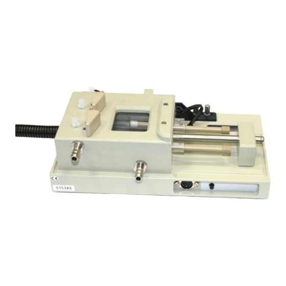
FIGURES Figure 1.1: the RX2000 ............................. 9 Figure 2.1: schematic of the RX2000 ........................10 Figure 2.2: the valve positions in the Load (left) and Drive (right) positions ............11 Figure 2.3: flow line closed (left) and open to waste reservoir (right) ..............12 Figure 2.4: flow line in its normal drive position (left) and normal empty position (right) ........ -
Page 9: Introduction
200 s can be followed. The RX2000 is easily the most accomplished device of its type, making use of the latest advances in stopped- flow design, combined with the simplicity, robustness and reliability of high quality instrument engineering. In one action the RX2000 mixes two reactants, fills a sample cell, stops the flow and simultaneously provides an output trigger. -
Page 10: Hardware
Figure 2.1: schematic of the RX2000 A schematic of the RX2000 is shown in Figure 2.1. The unit is designed to be compact and easy to use, allowing stopped-flow measurements to be obtained with UV-visible spectrometers, fluorimeters and CD polarimeters with the minimum amount of setting-up. -
Page 11: The Drive Syringes
The RX2000 uses three specially designed flow distribution valves, two of which are used to load the drive syringes and the third to control the removal of waste solution from the flow line. The two drive syringes have screw thread location whereas the reservoir, stopping and waste syringes use Luer location. -
Page 12: Waste Control Valve
RX2000 User Manual 2.4 Waste control valve Figure shows the waste control valve with the flow line closed, and with the flow line open to the waste reservoir, as used for flushing. Figure shows the flow line in the normal drive position, open to the stopping syringe, and the normal empty position, open to the stopping syringe and waste reservoir. -
Page 13: The Observation Cell
LCD. 2.6 Accessories The RX2000 Stopped-Flow Mixing Accessory can be upgraded with a pneumatic drive attachment, which may be used as required to provide powerful and reproducible stopped-flow drives. An optional anaerobic accessory is available to facilitate the rigorous exclusion of oxygen from the flow circuit if desired. -
Page 14: Operation
(the inlet port is the one located closer to the base). The temperature of the RX2000 is set by the fluid circulator. For guidance on the use of the circulator, see the User Manuals provided by the supplier. -
Page 15: Operation Using The Pneumatic Drive Accessory
3.3 Operation using the pneumatic drive accessory The RX2000 pneumatic accessory uses compressed gas to drive the drive syringes and could trap hands or clothing, causing injury to the user. Keep hands and clothing clear when performing a drive using the accessory. -
Page 16: Operation Using The Anaerobic Accessory
(Oxygen is held in a sintered matrix within the FEP components and can diffuse through FEP quite readily). Without the following precautions, carefully prepared deoxygenated reagents will take up oxygen from the FEP material used in the RX2000 Stopped-Flow Mixing Accessory. -
Page 17: Operation Using Ratio Mixing
To change one of the drive syringes (for example: when setting up a ratio mixing experiment) the thermostat bath must first be detached from the base of the instrument. Turn the RX2000 over and unscrew the thermostat bath: this is held on by 8 screws and requires a 3 mm hexagonal key. -
Page 18: Fluorescence Test Reaction
RX2000 User Manual sodium perchlorate Solution 1: 0.02M Iron (III) perchlorate and 0.08M Perchloric Acid in 0.5M Solution 2: 1mM Sodium thiocyanate in 0.5M sodium perchlorate. This reaction produces a large increase in absorbance at 434 nm with a doubling time of approximately 0.1 s.
Need help?
Do you have a question about the RX2000 and is the answer not in the manual?
Questions and answers