Table of Contents
Advertisement
Quick Links
User Manual
Chirascan Integrating Sphere
Applied Photophysics, Inc.
Applied Photophysics Limited
100 Cummings Center
21 Mole Business Park
Suite 440-C
Leatherhead
Beverly
Surrey
MA 01915
KT22 7BA
United States
United Kingdom
Tel: +1 978 473 7477
Tel: +44 1372 386 537
Email: info.usa@photophysics.com
Fax: +44 1372 386 477
Email: info@photophysics.com
www.photophysics.com
Advertisement
Table of Contents

Related Manuals for Applied Photophysics Chirascan Integrating Sphere


Summary of Contents for Applied Photophysics Chirascan Integrating Sphere
- Page 1 User Manual Chirascan Integrating Sphere Applied Photophysics, Inc. Applied Photophysics Limited 100 Cummings Center 21 Mole Business Park Suite 440-C Leatherhead Beverly Surrey MA 01915 KT22 7BA United States United Kingdom Tel: +1 978 473 7477 Tel: +44 1372 386 537 Email: info.usa@photophysics.com...
- Page 2 This document contains important safety information. Read this document and the Chirascan V100 Spectrometer User Manual before attempting to install or use the Chirascan Integrating Sphere. Failure to do so could result in death or serious injury. Document 4207Q266 V3.00 January 2018...
-
Page 3: Table Of Contents
CONTENTS USE OF THIS DOCUMENT ..........................4 HAZARD AND OTHER INDICATORS ....................... 5 ESSENTIAL SAFETY INFORMATION ....................... 6 CHIRASCAN INTEGRATING SPHERE INSTALLATION AND OPERATIONAL REQUIREMENTS ....7 GLOSSARY ................................ 8 1 INTRODUCTION ............................. 9 2 INSTALLATION ............................. 11 2.1 Preparing the Chirascan sample chamber ..................11 2.2 Installing the Integrating Sphere ...................... -
Page 4: Use Of This Document
Chirascan Integrating Sphere User Manual USE OF THIS DOCUMENT This document is intended to inform the operator of Applied Photophysics Integrating Sphere on its design, installation and operation with the Chirascan V100 Spectrometer. It is assumed that the user of this document is familiar with the operation of the Chirascan spectrometer, and with Applied Photophysics Pro-Data software. -
Page 5: Hazard And Other Indicators
Chirascan Integrating Sphere User Manual HAZARD AND OTHER INDICATORS HAZARD INDICATORS USED IN THIS DOCUMENT The sign to the left is used to indicate a hazardous situation, which, if not avoided, could result in death or serious injury. The sign to the left is used to indicate a hazardous situation, which, if not avoided, could result in minor or moderate injury. -
Page 6: Essential Safety Information
IN THIS DOCUMENT BEFORE ATTEMPTING TO INSTALL OR OPERATE THE INTEGRATNG SPHERE. IF YOU HAVE ANY QUESTIONS REGARDING THE OPERATION OF THE ACCESSORY, PLEASE CONTACT APPLIED PHOTOPHYSICS TECHNICAL SUPPORT AT THE ADDRESS SHOWN ON THE FIRST PAGE OF THIS USER MANUAL OBSERVE ALL SAFETY LABELS AND NEVER ERASE OR REMOVE SAFETY LABELS. -
Page 7: Chirascan Integrating Sphere Installation And Operational Requirements
Servicing Servicing of the Integrating Sphere should only be undertaken by qualified personnel. If you are in any doubt at all please contact the Applied Photophysics Technical Support at the address given on the first page of this User Manual. -
Page 8: Glossary
Chirascan Integrating Sphere User Manual GLOSSARY The following abbreviations may be found in this User Manual circular dichroism infrared Integrating Sphere ultraviolet HYPERLINKS This document contains hyperlinks between references (for example the Contents tables, or references to Sections or Figures in the text), and sources. To follow a link, place the cursor over the reference and use CTRL+click. -
Page 9: Introduction
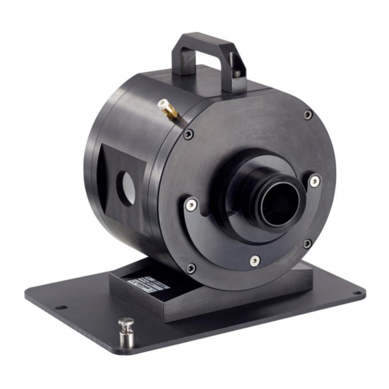
Chirascan Integrating Sphere User Manual 1 INTRODUCTION The Chirascan Integrating Sphere, shown in Figure 1.1, is designed to be used with the Chirascan V100 spectrometer. Figure 1.1: the Integrating Sphere Integrating spheres were developed early in the twentieth century, and were originally used to measure the total output of a light source, without reference to the original direction of the light. - Page 10 Chirascan Integrating Sphere User Manual Detector Port C Baffle Light, Port B Port A Figure 1.2: schematic of the Integrating Sphere (top view). The light enters at the light inlet port (Port A). In transmission mode it passes through the sample situated at the light inlet port, while the diffuse reflectance port (Port B) is occupied by a reflective plug.
-
Page 11: Installation
Chirascan Integrating Sphere User Manual 2 INSTALLATION 2.1 Preparing the Chirascan sample chamber Disconnecting electrical components without powering off the spectrometer can cause damage to the components. Power off the spectrometer before removing any accessories or installing the Integrating Sphere. - Page 12 Chirascan Integrating Sphere User Manual Fluorescence detector port Purge gas inlet ‘Y’ Connector Locking ring Locating peg CD detector port Support plate Locating peg Figure 2.1: the interior of the Chirascan sample chamber prepared for the Integrating Sphere Blanking plate Figure 2.2: the exterior of the Chirascan sample chamber prepared for the Integrating Sphere...
-
Page 13: Installing The Integrating Sphere
Chirascan Integrating Sphere User Manual 2.2 Installing the Integrating Sphere The temperature control unit stands on a mounting plate which locates on a support plate within the sample chamber. The unit on its mounting plate is shown in Figure (the diffuse reflectance port is to the rear of the Integrating Sphere when viewed from this angle). - Page 14 Chirascan Integrating Sphere User Manual Now reinstall the CD detector in the fluorescence port. Before installation the detector should be fitted with the spacer and ‘V’ ring (Figure 2.4). Slide the detector into the fluorescence port until the ‘V’ ring seals against the outer face of the Integrating Sphere detector port, and secure by tightening the detector port locking ring.
- Page 15 Chirascan Integrating Sphere User Manual Figure 2.6: interior of the sample chamber with all connections made (right view) Document 4207Q266 V3.00 January 2018 Page 15 of 23...
-
Page 16: Operation
Chirascan Integrating Sphere User Manual 3 OPERATION 3.1 Diffuse reflectance mode 3.1.1 Typical use In diffuse reflectance mode, the sample is in powder form, and is placed in the sample port directly opposite the light inlet port. The method is easier to use and requires less sample preparation than transmission mode, but normally uses more sample. - Page 17 Chirascan Integrating Sphere User Manual To load the sample, disassemble the holder and insert a 13 mm quartz plate into the well in the outer section, ensuring that it lies flat at the bottom of the well. Add the sample / diluent mix to a depth of about 0.5 mm (i.e.
-
Page 18: Acquiring A Spectrum
Chirascan Integrating Sphere User Manual Sample holder Aperture Figure 3.4: the Integrating Sphere configured for diffuse reflectance 3.1.4 Acquiring a spectrum It is difficult to distribute the powder entirely symmetrically in the holder. To minimize the effect of uneven sample distribution, the spectrum can be recorded at several positions and the results averaged. The sample holder is graduated with degree markings to help with this. - Page 19 Chirascan Integrating Sphere User Manual The results before data manipulation are shown in Figure and after averaging and baseline subtraction in Figure 3.6. L-alanine BaSO D-alanine Figure 3.5: CD spectra of D- and L-alanine and barium sulfate before data manipulation...
-
Page 20: Transmission Mode
Chirascan Integrating Sphere User Manual 3.2 Transmission mode 3.2.1 Typical use In transmission mode the sample is ground to a fine powder with a dispersant such as potassium bromide (KBr), or potassium chloride (KCl), and pressed to a transparent disc. This method requires less sample than for diffuse reflectance mode, but sample preparation is less straightforward and the method is not suitable for some samples. - Page 21 Chirascan Integrating Sphere User Manual Figure 3.8: the assembled transmission sample holder with sample in place The holder can now be mounted on the Integrating Sphere. Mount the holder in the position at the light inlet port on the Integrating Sphere. The holder mounts with the ‘O’ ring seal towards the sphere; ensure that it is seated down fully in position.
-
Page 22: Acquiring A Spectrum
Chirascan Integrating Sphere User Manual Sample holder reflective plug Figure 3.10: The Integrating Sphere configured for transmission 3.2.4 Acquiring a spectrum It is difficult to make discs for CD spectroscopy that are entirely symmetrical. To minimize the effect of sample orientation, the spectrum can be recorded at several positions and the results averaged. -
Page 23: Maintenance And Storage
Chirascan Integrating Sphere User Manual 4 MAINTENANCE AND STORAGE 4.1 Maintenance The internal surface of the Integrating Sphere is coated with a highly reflective material and the performance of the sphere will deteriorate if the surface becomes contaminated. Do not touch the surface or the white parts of the reflective plug used when the sphere is operating in transmission mode.
Need help?
Do you have a question about the Chirascan Integrating Sphere and is the answer not in the manual?
Questions and answers