
Subscribe to Our Youtube Channel
Related Manuals for IBR C100


Summary of Contents for IBR C100
- Page 1 M e t r o l o g y INSTRUCTION MANUAL C100 Column gauge Multi gauging Document No. : D2F201 002 Edition : June 2003 Copyright : Messtechnik GmbH & Co. KG...
-
Page 2: Table Of Contents
Instruction Manual C100 Contents 1. Introduction 1.1 General information ......................: 1.2 Measurement and display features ..................: 1.3 Front and rear panel ......................: 1.4 Dimensions .......................... : 1.5 Connectors round-up ......................: 1.6 Technical data........................: 2. Getting started 2.1 Delivered items........................ -
Page 3: Introduction
Instruction Manual C100 Introduction 1.1 General information The column gauge C100 is an electronic gauge supporting inductive probes, pneumatic converters, as well as sensors with analogue output voltages. The compact design of the microprocessor-based electro- nics allows manual and automatic selection of 1 ... 4 gauges to measure different work pieces or characteristics in an industrial environment. -
Page 4: Front And Rear Panel
Instruction Manual C100 Column display ranges ± 1,5000 mm ± 0,15000" The column display features 3 colours ( red, green, yellow ) ± 0,5000 mm ± 0,05000" with automatic colour selection corresponding to the given ± 0,1500 mm ± 0,01500"... -
Page 5: Dimensions
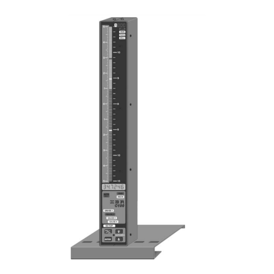
Instruction Manual C100 1.4 Dimensions 45 mm 5° Figure : Column display on footplate 102 mm 136.5 mm 1.5 Connectors round-up ( all accessories shown ) -
Page 6: Technical Data
Mode, Unit, Range, Programming light fields 16 light fields with changeable labelling Connections B/C100-ind2 measuring module for 2 2 DIN45322 sockets 5-pin and one 9-pin Sub-D socket with inductive probes, 2 analogue inputs & 2 outputs 2 analogue inputs and 2 outputs ( ± 1,5V/± 10000 Digit ) -
Page 7: Getting Started
Instruction Manual C100 Getting started 2.1 Delivered items The c olumn gauge is delivered with a power cable, a footplate ( with 2 screws M3x6 ), an instruction manual and a programming card. Further accessories, e.g. foot switches, adapters, etc. as listed in the delivery note. -
Page 8: Connecting The Pneumatic Converter Ae1
(max. 3). In the Probe mixing menu the two inductive probe inputs have the addresses A and B on the B/C100- ind2 module. Both analogue inputs have the addresses C and D. On the measuring module B/C100-... -
Page 9: Connecting A Foot Or Hand Switch
When two column gauges are linked to each other, the analogue outputs A and B of column no. 1 are connected to the analogue inputs C and D ( or vice versa A...D in the case of the B/C100-ana4 modules ) of the column gauges no. -
Page 10: Connecting A Pc, Multiplexer Or Statistic Printer
Instruction Manual C100 2.8 Connecting a PC, multiplexer or statistic printer To connect a PC ( COM 1 ...4 ), a multiplexer RS232 or statistic printer use the "RS232" Sub-D ( Opto RS232 format ) connector at the rear of the column gauge. -
Page 11: Programming The Column Gauge
Instruction Manual C100 Programming the column gauge All programming and settings of the column gauge are done with the 4 keys on the front panel. The user is taken step by step through the different menus with the help of the lamps and the numeric display. The programming follows a logic structure and becomes self-explanatory after a short study. -
Page 12: Quick Programming Guide For Programmers In A Hurry
Instruction Manual C100 3.3 Quick programming guide for programmers in a hurry Menu selection and programming 1. Use the PRG/CAL key to toggle from Measuring mode to Programming mode and vice versa. 2. In Programming mode the adjustable element is flashing. -
Page 13: Programming Menus
Instruction Manual C100 3.4 Programming menu Press the PRG/CAL key to switch from Measurement to Programming mode. - 'SEt OP.' flashes on the numeric display. The programming of the column gauge starts with the selection of the Measuring mode :... - Page 14 Instruction Manual C100 After pressing the ENTER key ( confirm flashing "Unit" ) in the 2nd menu you can select either „mm“ or „INCH" by pressing the key. Confirm with the ENTER key. Press the key to advance to the next menu.
- Page 15 Instruction Manual C100 The nominal value indicates the value to be chosen as zero point of the column display. If the nominal value is 20 mm ( SEt.Pnt. is set to 20 mm ) the column display will show a deviation of 0,1 mm for a work piece measuring of 20,1 mm.
- Page 16 Instruction Manual C100 In this menu the inductive probe inputs or voltage inputs A..D are assigned to the gauge ( or gauges ). Any combination of the inputs ( i.e. A + B, A - B, A+B - C+D, ... ) is possible.
-
Page 17: Basic Settings / Setup Menu
Instruction Manual C100 Basic settings / Setup menu The Setup menu ( „SEtUP“ ) contains all basic settings which are usually introduced only at the first start-up. The basic factory settings are marked by * throughout the menus. rESoL. In this menu you can select the resolution of the numeric display for the Measuring mode. - Page 18 Instruction Manual C100 triGG. In this menu you can choose the control of numeric and column displays via the foot switch. - Continuous display update with measured values. The foot switch does not effect the display output. trAnS - By pressing the foot switch you start a measurement cycle with transfer of the result to the displays.
- Page 19 Instruction Manual C100 rS 232 In this menu the data output via RS232 interface is programmed. So.C. oFF / on Set continuous data output on RS232 oFF - Continuous data output is disabled - Continuous data output is enabled Notice :...
- Page 20 Instruction Manual C100 tol.LEd In this menu flashing of tolerance points when measured values are out of tolerance is enabled or disabled. Flash = The tolerance points are flashing if measured values are out of the green area. = Tolerance points do not flash.
-
Page 21: Restoring Factory Settings
Instruction Manual C100 Restoring factory settings Resetting the column gauge to the factory settings is done in Measuring mode. ( If necessary, leave the Programming mode by pressing the PRG/CAL key ). Press the "PRG/CAL" and "ENTER" keys simultaneously and hold them down for approx. 5 sec until on the numeric display "rESEt"... - Page 22 1...4 ). Error messages are intended to help our service department quickly analyse the reasons for your difficulties. Please, press <ENTER>- to restart the column gauge or switch the column gauges off and on. If the error message reappears, contact the IBR-Service department.
-
Page 23: Working With The Column Gauge
Instruction Manual C100 Working with the column gauge 4.1 First start-up Start by fitting the footplate and connecting the accessories ( inductive probes, foot switches, etc. ). Follow the instructions given in chapter 2 of this manual. The next step will be programming of the column gauge for your application. Follow the instructions given in chapter 3 of this manual. -
Page 24: Zero Adjustment Of Gauges
Instruction Manual C100 4.4 Zero adjustment of gauges Start by placing the master in the measuring fixture. Make sure that the column gauge is in measuring mode. If necessary press the PRG/CAL key to leave the Programming mode. The Setup menu "AutoCA"... -
Page 25: Calibration Of Probe Inputs
Notice : If the same probe or analogue input ( A...D ) is selected on several gauges ( gauge 1...4 ) and the "Automatic gauge selection" is switched on, the C100 shows “Err. 8' on the numeric display. Because the probe or analogue input changes several gauges simultaneous the... -
Page 26: Rs232 Interface
Instruction Manual C100 RS232 interface The column gauge has an RS232 interface to support data output to computers, multiplexers, statistic printers and so on. The plug connector ( 9-pin Sub-D ) is mounted at the rear of the column gauge and is marked RS232. -
Page 27: Transfer Of Measured Values
Instruction Manual C100 Example : PC Programme ( DOS, BASIC ) 100 REM DATA REQUEST WITH DTR-LINE 110 OPEN "COM1,4800,E,7,2" FOR RANDOM AS #1 ... open COM device 120 OUT &H03FC,&H000A ... reset DTR line ( COM1=3FC / COM2=2FC / COM3=3EC / COM4=2EC ) 130 DELAY 0.1... -
Page 28: Importing Measurement Values Into Windows Applications
Instruction Manual C100 5.5 Importing measurement values into Windows applications To import measurement values into 32-bit Windows applications the IBR_Device Driver Kit = IBR_DDK.DLL is available free of charge on our web side www.IBRit.com The IBR_DDK.DLL supports both an API function set and COM function set ( ActiveX ). Examples in C++, Delphi and Visual Basic are included. -
Page 29: Pin Assignments Of Connectors
Instruction Manual C100 Pin assignments of male connectors 6.1 Connectors of the column gauge... -
Page 30: Plug-In Terminal Blocks
Instruction Manual C100 6.2 Plug-in terminal blocks for accessories... - Page 31 Instruction Manual C100...
-
Page 32: Accessories And Order Information
85...260V, incl. footplate and manual. B/C100-ind2 B/C100 measuring module to connect 2 inductive probes ......F220 010 2 analogue inputs and outputs ( Tesa halfbridge and compatible ) B/C100 measuring module to connect 2 inductive probes, ...... - Page 33 Opto coupler adapter with plug-in terminal block ..........F603 003 SP4-AC Accu-module incl. accu ( F220 110 ) for B100 and C100 ......F220 100 ( On exchange with integrated power supply module ) Universal-charger for Lithium Ionen Accus ( VW-VBD1E ) ......
-
Page 34: Safety Instructions
Any modification and procedures concerning the instrument are permitted only with the prior written consent of IBR Messtechnik GmbH & Co. KG and must be carried out by competent staff. Opening the case or tampering with the device without prior permission will lead to the loss of the guarantee and free the producer from all liabilities. -
Page 35: Declaration Of Conformity
Instruction Manual C100 9. Declaration of conformity Thank you very much for your confidence in purchasing this product. We herewith certify that it was manufactured and inspected in our works. We declare under our sole responsibility that this product is in conformity with technical data as specified in this instruction manual.
Need help?
Do you have a question about the C100 and is the answer not in the manual?
Questions and answers