
Related Manuals for IBR C100-AE


Summary of Contents for IBR C100-AE
- Page 1 M e t r o l o g y INSTRUCTION MANUAL C100-AE Column gauge Incl. pneumatic converter Document No. : D2F202 001 Edition : September 2004 Copyright : Messtechnik GmbH & Co. KG...
-
Page 2: Table Of Contents
Instruction Manual C100-AE Contents 1. Introduction 1.1 General information ......................: 1.2 Measurement and display features ..................: 1.3 Front and rear panel ......................: 1.4 Dimensions .......................... : 1.5 Connectors round-up ......................: 1.6 Technical data........................: 2. Getting started 2.1 Delivered items........................ -
Page 3: Introduction
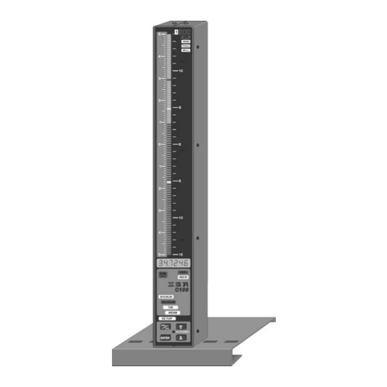
The three- coloured column display features programmable tolerance points and supports an accurate assessment of the processing quality. The C100-AE is an ideal tool for manual examination of measurement values or automatic gauging applications with computers or PLC units. -
Page 4: Front And Rear Panel
Instruction Manual C100-AE Column display ranges ± 1,5000 mm ± 0,15000" The column display features 3 colours ( red, green, yellow ) with ± 0,5000 mm ± 0,05000" automatic colour selection corresponding to the given ± 0,1500 mm ± 0,01500"... -
Page 5: Dimensions
Instruction Manual C100-AE Dimensions 45 mm 5° Figure : Column display on footplate 102 mm 136.5 mm Connectors round-up ( all accessories shown ) -
Page 6: Technical Data
Quick coupling for PU hose 8/6 mm Air pressure supply ( input pressure regulator ) 4 - 8 bar / 60 - 120 psi Air pressure ( C100-AE input ) 2 - 3 bar / 30 - 45 psi ( filtered air < 5µm ) -
Page 7: Getting Started
2.3 Mounting the air filter and pressure regulator To mount the filter and the pressure regulator a mounting kit is supplied together with the C100-AE. The kit consists of a wall bracket and a nut to fasten the filter / regulator to the bracket. -
Page 8: Pressure Connection
2.4 Pressure connection The connection between the mounted pressure regulator and the pressure input of the C100-AE is done by the delivered PU hose 8/6 mm ( 2 m ). The hose is pushed on both sides of the connectors and is secured by a nut. -
Page 9: Connecting A Foot Or Hand Switch
Instruction Manual C100-AE 2.6 Connecting a foot or hand switch Foot and hand switches can be connected to both the RS232 male connector and the Tol.-Out socket, to be found at the rear of the column gauge. Please, use only the foot and hand switches supplied with the instrument. -
Page 10: Connecting A Pc, Multiplexer Or Statistic Printer
Instruction Manual C100-AE 2.8 Connecting a PC, multiplexer or statistic printer To connect a PC ( COM 1 ...4), a multiplexer or statistic printer use the "RS232" Sub-D (Addresses 1...127) connector at the rear of the column gauge. RS232 For pin assignment see chapter 6... -
Page 11: Programming The Column Gauge
Instruction Manual C100-AE Programming the column gauge All programming and settings of the column gauge are done with the 4 keys on the front panel. The user is taken step by step through the different menus with the help of the lamps and the numeric display. The programming follows a logic structure and becomes self-explanatory after a short study. -
Page 12: Quick Programming Guide For Programmers In A Hurry
Instruction Manual C100-AE 3.3 Quick programming guide for programmers in a hurry Menu selection and programming 1. Use the PRG/CAL key to toggle from Measuring mode to Programming mode and viceversa. 2. In Programming mode the adjustable element is flashing. -
Page 13: Programming Menu
Instruction Manual C100-AE Programming menu Press the PRG/CAL key to switch from Measurement to Programming mode. 'SEt OP.' flashes on the numeric display. The programming of the column gauge starts with the selection of the measuring mode. Standard-Measuring mode ( static measurements ) Dyn. - Page 14 Instruction Manual C100-AE The programming of a master value is base of the Automatic Zero Adjustment. On Automatic zero adjustment ( do this by placing the master piece into the measuring fixture and press keys simultaneously during Measuring mode ) the master value will be taken as the measured value and appears on the numeric display.
- Page 15 Instruction Manual C100-AE In this menu you can set a maximum of 4 tolerance points representing relative deviation from the nominal value. Programming starts by selecting one of the four tolerance marks on the column display : + red upper tolerance ( red ) + yellow upper tolerance ( yellow ) –...
-
Page 16: Basic Settings / Setup Menu
Instruction Manual C100-AE Basic settings / Setup menu The Setup menu ( „SEtUP“ ) contains all basic settings which are usually introduced only at the first start- The basic factory settings are marked by * throughout the menus. rESoL. In this menu you can select the resolution of the numeric display for the Measuring mode. - Page 17 Instruction Manual C100-AE triGG. In this menu you can choose the control of numeric and column displays via the foot switch. - Continuous display update with measured values. The foot switch does not effect the display output. trAnS - By pressing the foot switch you start a measurement cycle with transfer of the result to the displays.
- Page 18 Instruction Manual C100-AE rS 232 In this menu the data output via RS232 interface is programmed. So.C. oFF / on Set continuous data output on RS232 oFF - Continuous data output is disabled - Continuous data output is enabled Notice :...
- Page 19 Instruction Manual C100-AE tol.LEd In this menu flashing of tolerance points when measured values are out of tolerance is enabled or disabled. Flash = The tolerance points are flashing if measured values are out of the green area. = Tolerance points do not flash.
-
Page 20: Restoring Factory Settings
Instruction Manual C100-AE 3.6 Restoring factory settings Resetting the column gauge to the factory settings is done in Measuring mode. ( If necessary, leave the Programming mode by pressing the PRG/CAL key ). Press the "PRG/CAL" and "ENTER" keys simultaneously and hold them down for approx. 5 sec until on the numeric display "rESEt"... - Page 21 ( n = 1...4 ). Error messages are intended to help our service department quickly analyse the reasons for your difficulties. Please, press <ENTER>- to restart the column gauge or switch the column gauges off and on. If the error message reappears, contact the IBR-Service department.
-
Page 22: Working With The Column Gauge
Instruction Manual C100-AE Working with the column gauge 4.1 First start-up Start by fitting the footplate and connecting the accessories ( air pressure, gauge head, foot switches, etc. ). Follow the instructions given in chapter 2 of this manual. The next step will be programming of the column gauge for your application. Follow the instructions given in chapter 3 of this manual. - Page 23 Improved restrictor adjustment on C100-AE - Gauges The C100-AE gauge must be set into Measuring mode. If it is not set to Measuring mode, please press the PRG/CAL key to leave the Programming mode.
-
Page 24: Automatic Gauge Calibration
Instruction Manual C100-AE 4.4 Automatic gauge calibration By airgauging normaly the automatic gauge calibration with 2 master is used, because all offsets and amplification errors are automatically corrected. Start by placing one of the two masters in the measuring fixture and make sure that the digital gauge is in measuring mode. -
Page 25: Maintenance And Care
It is important to supervise especially by automatic measuring systems the pressure supply. The supervision of the pressure supply is independent to the IBR - pneumatic and measuring elements. 7. RS232 interface The column gauge has an RS232 interface to support data output to computers, multiplexers, statistic printers and so on. -
Page 26: Requesting Measured Values
Instruction Manual C100-AE Requesting measured values The column gauge supports both data request variants of the Opto RS232 interface. 1. Data request via handshake lines ( unidirectional Opto RS 232 ) Impulse diagram : Time 100 msec Connection wirings Column gauge : RS232 External device □... -
Page 27: Transmission Of Measured Values
Instruction Manual C100-AE Example : PC-Programme ( DOS, BASIC ) 100 REM REQUEST MEASUREMENT VALUE BY "?" 110 OPEN "COM1,4800,E,7,2" FOR RANDOM AS #1 ... open COM device 120 PRINT#1, "?" +CHR$(13); … request measurement value 130 INPUT #1,A$ … input measurement value 140 PRINT A$ ... -
Page 28: Importing Measurement Values Into Ms-Excel
Instruction Manual C100-AE 7.6 Importing of measurement values into MS-EXCEL The IBREXDLL.XLS is an EXCEL workbook for the component- or characteristic depending data collection into Excel tables. Therefore extensive possibilities for data collection, formatting and organisation in a table without limitation of the standard Excel functions are supplied. -
Page 29: Pin Assignments Of Connectors
Instruction Manual C100-AE Pin assignments of connectors 8.1 Connectors of the column gauge 8.2 Plug-in terminal blocks... - Page 30 Instruction Manual C100-AE...
-
Page 31: Accessories And Order Information
Instruction Manual C100-AE Accessories and order information Designation Article-Number C100-AE Column gauge incl. pneumatic measurement converter, air filter F202 001 and pressure regulator 6-digit numeric display, 100 bar column display ( 3-colour) LED´s for unit, range and function display, RS232, trigger input digital outputs, switching power supply for 85...260V, incl. -
Page 32: Safety Instructions
Any modification and procedures concerning the instrument are permitted only with the prior written consent of IBR Messtechnik GmbH & Co. KG and must be carried out by competent staff. Opening the case or tampering with the device without prior permission will lead to the loss of the guarantee and free the producer from all liabilities. -
Page 33: Declaration Of Conformity
Instruction Manual C100-AE 11. Declaration of conformity Thank you very much for your confidence in purchasing this product. We herewith certify that it was manufactured and inspected in our works. We declare under our sole responsibility that this product is in conformity with technical data as specified in this instruction manual.
Need help?
Do you have a question about the C100-AE and is the answer not in the manual?
Questions and answers