
Related Manuals for IBR C200


Summary of Contents for IBR C200
- Page 1 M e t r o l o g y INSTRUCTION MANUAL C200 Column gauge Document No. : D2MF232 001 Edition : August 2011 © Copyright : Messtechnik GmbH & Co. KG...
-
Page 2: Table Of Contents
2.3.1 Removal of C200 column cover ................. : 2.3.2 Connecting the IMBus modules ................. : 2.3.3 Fitting of bus terminator ....................: 2.3.4 Fitting IMBus modules into the C200 column gauge ..........: 2.3.5 Fitting of C200 column cover ..................: 2.4 Measuring input addresses ....................: 2.5 Connecting several column gauges .................. - Page 3 Instruction Manual C200 5. The RS232 interface 5.1 Transmission format and wiring ................... : 5.2 Data format ........................... : 5.3 Table of commands ......................: 5.4 Requesting measurement values ..................: 5.5 Transmission of measurement values ................. : 5.6 Importing measurement values into Windows applications ..........: 5.7 Importing measurement values into MS-EXCEL ..............
-
Page 4: Introduction
The new Bus system of the C200 provides solutions for most sophisticated measuring applications, simply by in- terconnecting several column gauges. -
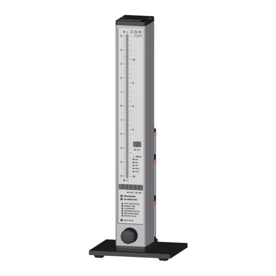
Page 5: Front And Rear View
In the measuring mode, the selected column display range is indicated on the numeric display when the Encoder but- ton is pressed longer than 2 seconds. User-defined column display ranges can be programmed using the PC software C200_PC ( provided by IBR free of charge ). Front and rear view... -
Page 6: Dimensions
Instruction Manual C200 1.4 Dimensions Picture : Column display with base 1.5 Hole pattern for interconnection... -
Page 7: Technical Data
(16 detents per rotation) Dimensions W x H x D / Weight 56 x 418.5 x 86 mm / 1340g ( incl. base C200 incl. base, IMB-ps2 and IMB-mc1 = 1650g Electrical characteristics Power supplies: IMB – ps2 Primary switched power supply 100 to 240VAC, 45 to 60Hz IMB –... -
Page 8: Getting Started
8 probes, air plug gauges, sensors and digital measuring instruments. The respective modules of the IM- Bus series can be fitted to the rear panel of the C200 in order to connect probes, sensors and gauges. See IMBus Module Overview, chapter 2.12 !!! 2 DIN 7984 M3 x 8 2.3.1... -
Page 9: Connecting The Imbus Modules
The C200 column gauge can read in a maximum of 8 connected sensors or measuring instruments. If several C200 are to be connected, the IMB-cas adapter cable ( No. 1 ) has to be fitted first, followed by the power supply module ( No. 2 ), then the IMB-mc1 measuring controller and subsequently the IMBus measuring and interface modules in any chosen order. -
Page 10: Fitting Of Bus Terminator
Instruction Manual C200 Important : Should an IMBus module already be equipped with bolts ( e.g. IMB-ps2 when using an IMB-cas , please replace the bolts with 2 cross-recessed screws SH-UNC / 4-40*9.5 adapter cable ) in order to enable connecting of modules. -
Page 11: Fitting Imbus Modules Into The C200 Column Gauge
C200 column section. Finally the module package is screwed to the column base. 2.3.5 Fitting of C200 column cover. Place the column cover on top of the C200 and fix with two Allen screws ( M3 x 8). !!! Do not overtighten screws !!! -
Page 12: Measuring Input Addresses
When you use an IMB-rf1 module together with other IMB-modules in one C200, then you must install the IMB-rf1 module as the last module of the C200 ( upper position ). Because the C200 supports only eight chan- nels and the IMB-rf1 has already eight channels, all other... -
Page 13: Connecting Several Column Gauges
Instruction Manual C200 2.5 Connecting several column gauges IMB-cas type adapter cables are utilized to connect several column gauges. The adapter cables fulfil two tasks : 1.) Transferring the supply voltage from the first column gauge to the next. One power supply module can supply power to a maximum of 3 column gauges, depending on the connected probes, sensors and measuring instruments. -
Page 14: Power Supply Connection
The module allows quick battery replacement. Rechargeable batteries with capacities of 1850 / 4000 and 5500 mAh are available. ( Example : C200 with 2 inductive probes and a 4000 mAh battery pack can operate for approx. 12 to 15 hours ) -
Page 15: Connecting A Foot Or Hand Switch
Instruction Manual C200 2.7 Connecting a foot or hand switch The foot or hand switches are connected to the Sub-D ports Ft1 and Ft2 of the IMB-mc1 measuring controller. Foot and hand switches can be cascaded in order to synchronize several column gauges ( e.g. -
Page 16: Connecting A Pc, Multiplexer Or Statistic Printer
Instruction Manual C200 2.9 Connecting a PC, multiplexer or statistic printer A PC , a multiplexer or a statistic printer can be connected at the rear panel of the ( COM 1… 8, USB ) column gauge via the RS232 Sub-D port of the IMB-mc1 measuring controller. -
Page 17: Connection Of Probes, Air Plug Gauges, Sensors And Measuring Instruments
A maximum of 8 measuring inputs can be handled by the C200. It is possible to connect more than 8 inputs, however, the additional inputs are ignored. The RUN LED on the bus terminator connector... - Page 18 For more information see IMB-ae1 Manual, Doc. D2MF122 081 Example 4 : Connection of different probes, gauges, sensors and measuring instruments The example depicts a C200 configuration for connection of 2 inductive probes ( IMB-im2 ), 2 incremental probes with...
-
Page 19: Imbus Modules At A Glance
If an error is detected during the self-test, the numeric display will indicate an er- ror message. If the display remains dark, after the C200 column gauge was switched on, check both, the VCC and RUN LEDs on the bus terminator connector. -
Page 20: Programming The Column Gauge
Instruction Manual C200 Programming the column gauge The rotary encoder on the front panel is used to make all settings and carry out any programming. During programming the user is guided through the individual menus, step by step, and prompted by the LED and numeric displays. -
Page 21: Quick Programming Guide For Programmers In A Hurry
Instruction Manual C200 3.3 Quick programming guide for programmers in a hurry Menu selection and programming 1. Turn the encoder clockwise ( CW ) to switch to the programming mode. Turn the encoder counterclockwise ( CCW ) to exit the programming mode. -
Page 22: Description Of The Calibration Mode
Attention : Once a gauge has been calibrated with 2 masters, the amplification ( pneumatic : spread ) determined for this gauge is permanently stored inside the C200. Hence, for measuring operation the C200 could be switched to zero adjustment using only 1 master. -
Page 23: Probe Setup
Instruction Manual C200 3.4.2 Probe setup Inductive probes achieve their greatest degree of accuracy within a comparatively small measuring range only. It is therefore extremely important to carefully set up the probes at the electric zero point. On selection of the AdJuSt menu, the two-digit numeric display shows the measuring input P1 and the six-digit numeric display indicates the “raw value”... -
Page 24: Description Of The Programming Menu
Instruction Manual C200 3.5 Description of the programming mode Turn the encoder clockwise ( CW ) to switch from the Measuring Mode to the Programming Mode. - The six-digit numeric display indicates ‘ProGr.’. Programming menus : You can select the first menu by pushing the encoder button. - Page 25 Instruction Manual C200 Turn the encoder to select the desired number of the flashing point and then confirm by pushing the encoder button. The nominal value determines the value at which the zero point is indicated on the column (no deviation) display.
- Page 26 Instruction Manual C200 The MEASURING INPUTS menu enables assigning the measuring inputs ( P1 to P8 ) to the currently se- lected gauge ( C1…C8 ). The 8 inputs can be linked in any order ( e.g.: P1+P2, P1-P2, P1+P2 - P3+P4, etc. ).
- Page 27 In addition to the static measuring mode, the C200 column gauge also has several dynamic measuring modes available. Each of the 8 gauges ( C1 to C8 ) can be assigned its own measuring mode without any restriction.
- Page 28 Instruction Manual C200 Turn the encoder to select the desired number of the flashing point and then confirm by pushing the en- coder button. - The first master value is programmed - The numeric display now flashes and indicates “2nd on” or “2nd off”. Turn the encoder to select...
-
Page 29: Basic Setup
Instruction Manual C200 3.6 Basic setup The Basic Setup menu comprises all basic device settings which are usually only programmed during the initial operation. ∗ The basic factory setting is identified by an in the individual menus. GAGES Push the encoder button to select the menu. Turn the encoder to browse through the individ- ual gauges from C1 to C8. - Page 30 C200 In the Basic Setup menus L2 to L5 controlling of the C200 via the encoder button and the foot or hand switch connections Ft1, Ft2 as well as the IMB foot switch Ft3 is set. The encoder button and each one of the 3 foot or hand switch connections can be assigned any function from the list.
- Page 31 The activation of the trAnS mode freeze-frames the numeric and column display of the C200 column gauge. Every time a programmed input ( Encoder button, Ft1, Ft2, Ft3 ) is actuated, the currently measured value will be displayed. hold The activation of the hold mode effects that the display is freeze-framed while the programmed input is actuated ( Encoder button, Ft1, Ft2, Ft3 ).
- Page 32 Instruction Manual C200 GrAdE The grading mode can be activated or deactivated independently for each gauge ( C1 to C8 ) in this menu. The number of grading groups ( classes ) can be set from 1 to 30 and deter- mines in how many, equal fields the tolerance range is split.
-
Page 33: Restoring Factory Settings
Instruction Manual C200 PASS.Cd. For the protection of calibration and / or programming data, password protection can be activated in this menu. The numeric display will prompt the assignment of a six-digit password for password protection of calibration or programming data. -
Page 34: Error Messages / Corrective Actions
Instruction Manual C200 3.8 Error messages / Corrective actions The numeric display indicates Operating and Programming Errors caused by the user as well as System Errors of the column gauge. 3.8.1 Operating and programming errors Err. xx : error message ( Err ), error number ( xx ) -
Page 35: System Errors
System errors are displayed in the event of hardware problems. These error messages assist our service department in analysing the problem. Switch off the device and then switch it on again. If the error message recurs, please contact the IBR service department. Error... -
Page 36: Working With The Column Gauge
Instruction Manual C200 Working with the column gauge 4.1 Initial operation Start by fitting the base and connecting the accessories ( probes, foot switches, etc. ). Follow the instructions given in chapter 2 of this manual. Then programme the column gauge for your application. -
Page 37: Restrictor Adjustment On Imb-Ae1 Moduls
Instruction Manual C200 4.4 Restrictor adjustment on IMB-ae1 moduls Restrictor adjustment with 2 masters : Use the encoder to select the “CALIBRATION” menu. The calibration menu is password protected, if the numeric display indicates “PASS.Cd.”. ( See BASIC SETUP “LA – PASS.Cd.” ) Select the Adjust function by turning the encoder ( “AdJuSt”... -
Page 38: Automatic Zero Adjustment Of Gauges
This function is programmed in the menu L9 of the “BASIC SETUP”. 4.7 Multi gauging ( C1 … C8 ) The C200 column gauge allows programming up to 8 independent gauges ( C1 to C8 ). The unit, resolution, nominal size, tolerance, measuring mode and master values can be programmed for each individual gauge. -
Page 39: The Rs232 Interface
Request current measured value displayed on numeric display "1 … 8 <cr>" Selection of gauge C1 ... C8 "I <cr>" Request type of device / version: "C200 V1.0 <cr>" "S <cr>" Start / Stop dynamic measurement "Z <cr>" Executes zero adjustment Note : This command cannot be used to execute a gauge calibration with two masters "A <cr>"... -
Page 40: Requesting Measurement Values
IBREXDLL enables reading measurement data in MS-Excel and assigning that data freely to the cells of any Excel workbook. The measurement data can come from any IBR interface and measuring devices. The collected data can later be analysed statistically by control charts, histograms and so on. -
Page 41: Connector Pin Assignments
Instruction Manual C200 Connector pin assignments 6.1 IMB-mc1 measuring controller connectors... -
Page 42: Terminal Blocks Of The Accessories
Instruction Manual C200 6.2 Terminal blocks of the accessories Adapter : OA-adp FTRG ( Trigger input ) ( Ground ) OUT 5 ( Lower tolerance limit, red ) OUT 4 ( Lower intervention limit, yellow ) OUT 3 ( Measured value OK, green ) -
Page 43: Accessories And Ordering Information
Instruction Manual C200 7. Accessories and ordering information Designation Part Number C200 Column gauge without measuring module F232 001 Column gauge - basic module with 3-colour column display ( 103+2 Seg. ), digital measured value display, base, programming card and manual IMB-mc1 Measuring controller for IMBus display modules with RS232 interface, .... - Page 44 Instruction Manual C200 Designation Part Number IMB-ae1 Measuring module to connect 1 pneumatic gauge head ......... F122 081 hose connector ( 4/6 mm ) for gauge head AE-FC1 Pressure regulator with filter, quick-release fastener for hose ......F330 011 connection LW9, mounting bracket and 2 m long compressed-air hose 8/6 AE-FF Filter unit with centrifugal separator, sintered filter element ( 5 µm ), ....
- Page 45 Cable to connect to USB ports, incl. driver software ........F601 021 for COM port emulation IBRit-rf1-232 Radio module for wireless data transmission from C200 gauges to a PC ..F604 008 RSD-adp RS232 cable with converter for Mitutoyo Digimatic interface ......
-
Page 46: Safety Instructions
6. Any modification to or change in procedures concerning the instrument is permitted only with the prior written consent of IBR Messtechnik GmbH & Co. KG and must be carried out by trained staff. Unauthorised opening of the instrument or tampering with the device shall void the guarantee and exempt the manufacturer from any liability. -
Page 47: Declaration Of Conformity
Instruction Manual C200 Declaration of conformity Thank you very much for your confidence in purchasing this product. We herewith certify that it was manufactured and inspected in our works. We declare under our sole responsibility that this product is in conformity with technical data as specified in this instruction manual.
Need help?
Do you have a question about the C200 and is the answer not in the manual?
Questions and answers