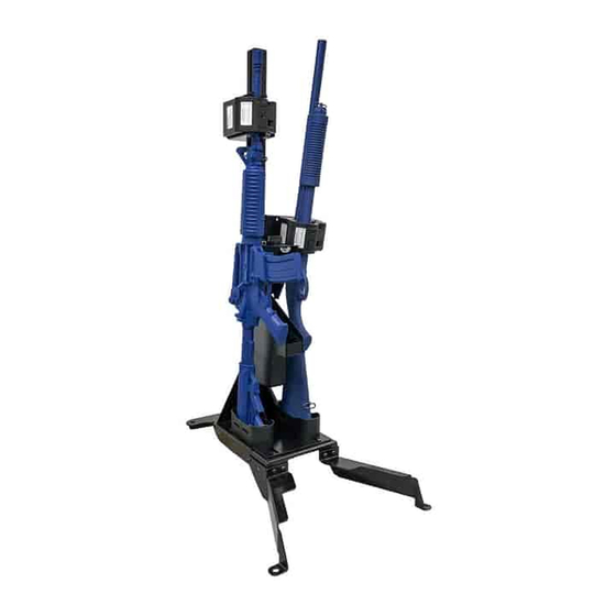
Summary of Contents for Pro-gard Products GVM8116FT
- Page 1 INSTALLATION GUIDE GV M8116F T S E LF S UP PO RTI NG GUN R A CK 2016- 2020 FO RD F 150 SUP ER C R EW S T R O N G R E L I A B L E S E C U R E pro-gard.com 800.480.6680...
- Page 2 THESE COMPONENTS ARE REQUIRED TO INSTALL THE PRO-GARD G7047 SELF SUPPORTING STAND AND TRI-LOCK GUN RACK Tri-Lock Gun Rack GVPMXXXX G8116FT Self Supporting Stand Refer to the diagram on the last page of these instructions to verify all parts were received. The following tools will be required to complete the installation.
- Page 3 VI. Installing the Tri-Lock gun rack (Requires Pro-gard self-supporting mounting base) A. Place the intended guns into the gun rack and make adjustments to fit. This will allow more access than when the rack is in the vehicle, but the rack can be adjusted after installed inside the vehicle as well. B.
- Page 4 VII. Self-Supporting Installation A. For self-supporting installations, remove the four bolts that secure the butt plates to the base of the gun rack. Then rest the gun rack to the self supporting stand, loosely attach the gun rack and adjust it and the butt plates as necessary from front to back.
-
Page 5: Installation Complete
IX. Gun lock switch and timer installation. A. We suggest mounting the momentary release button in a concealed location that can be easily reached by the officer, but would be hidden in case an unathorized entry occurs. B. Connect the gun lock wiring as shown in the diagram below. NOTE: Pro-gard requires the use of a 10 AMP fuse between the power source and gun lock circuit or the warranty will be voided! - Page 6 DIMENSIONS ARE IN INCHESTOL ON ANGLES 1° Angle ENGR 1: PART DESCRIPTION: Pro-Gard Products without the specific MATERIAL: Projection written authorization of Pro-gard Products. NOTE: ENGR 2: FREE OF SHARP EDGES...
- Page 7 Tri-Lock Gun Rack PARTS LIST ITEM PART NUMBER DESCRIPTION 3GVM201-01 RACK BASE WELDMENT 3GVM001-04 1.5" X 1.5" X 38" LG. ALUM EXTRUSION **G4962-002 BUTT PLATE - BLACK NYLON **G4963-002 RUBBER BUTT PLATE PAD 3GVM201-02 LOCK MOUNTING BRACKET - PASSENGER 3GVM201-03 LOCK MOUNTING BRACKET - DRIVER **G4904-NPG R GUN LOCK...


Need help?
Do you have a question about the GVM8116FT and is the answer not in the manual?
Questions and answers