
Related Manuals for Niles IRP-2+


Summary of Contents for Niles IRP-2+
- Page 1 M O D E L IRP2+ IRP2+ IRP2+ INFRARED EXTENDER MAIN SYSTEM UNIT I N S T A L L A T I O N & O P E R A T I O N G U I D E...
-
Page 2: Table Of Contents
Main System Unit via a 2-conductor shielded cable. Generally, sensors are placed so that you can easily and naturally point your remote control directly at them. Niles offers an array of easily concealable sensors: wall-mount, ceiling-mount, sur- face-mount and table-top. - Page 3 N N F F R R A A R R E E D D IR Controllable A/V Components Figure 1 In a typical system, the IRP2+ provides for the connection of up to two remote room sensors (or keypads) and will control a maximum of eight audio/video components via its flasher connections (four IRC-1 flashers or eight IRC-2 flashers).
-
Page 4: Features And Benefits
Built in “Status” generator broadcasts the amplifier “on/off” power status over existing IR wiring to provide power status display when used with other Niles products like the IntelliPad that feature status display LED’s. Screw connectors simplify installation. Printed circuit board design assures high reliability. -
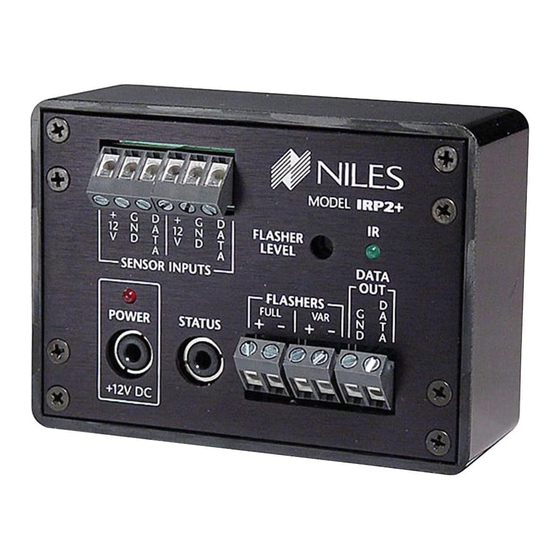
Page 5: Irp2+ Parts Guide
N N F F R R A A R R E E D D IRP2+ Parts Guide Power Supply is a UL listed and approved 12vDC wall adapter. Red Power Test LED enables you to test for proper power supply operation and shorts between + and GND on... -
Page 6: Installation Considerations
N N F F R R A A R R E E D D X X T T E E N N D D E E R R Installation Considerations Placement of the IRP2+ IMPORTANT Place the IRP2+ conveniently close to the equipment it will be con- Do not place the trolling. - Page 7 N N F F R R A A R R E E D D Wiring From every IR Sensor location you must “home-run” a cable back to the IRP2+. Home run means that an individual cable is connected between each IR Sensor and the IRP2+. See Figure 4. Remotely Located Room 1 IR Sensors...
- Page 8 Flasher Cable Niles infrared flashers come supplied with a 10 foot 2-conductor 22 gauge cable. Should you need to extend it, use a 16 gauge 2-conduc- tor cable (“zip-cord”). Shielding is not necessary for a flasher. Flasher wires can be extended up to 200 feet.
-
Page 9: Installation
N N F F R R A A R R E E D D Installation Before you begin, make sure that the sensor/keypad cables, the flash- er cables and the 12vDC power supply cable will all reach the pro- posed location of the IRP2+. Mark the cables with labels describing where the cable originates (rather than which terminal on the IRP2+ it should connect). - Page 10 N N F F R R A A R R E E D D X X T T E E N N D D E E R R STEP 1. Connect and test the power supply. If it tests OK, unplug the connector from the power socket and pro- ceed.
- Page 11 N N F F R R A A R R E E D D X X T T E E N N D D E E R R STEP 4. Connect the flashers to the flasher outputs. If you need to extend the wire, use a 2-con- ductor 16 gauge or larger (See Tech Tip on page 6).
-
Page 12: Testing The Ir Extender System
Operation should be identical to standing in front of the compo- nent with the remote control pointed directly at the sensor window. 3. Maximum Range between the Remote Control and the Niles IR Sensor is similar to the maximum range between the Remote Control and the A/V component’s IR sensor. -
Page 13: Trouble-Shooting
N N F F R R A A R R E E D D Troubleshooting Guidelines There are four basic problems which prevent proper operation. In the order of probability the problems are: Bad Connections or Wiring If the connections or wiring are wrong, loose, shorted or open the system will not operate properly. - Page 14 - - M M N N F F R R A A R R E E D D X X T T E E N N D D E E R R A A I I N N Y Y S S T T E E M M N N I I T T Optical Feedback Loop If you have an IR sensor in the same room as a flasher, and you have...
-
Page 15: Troubleshooting Guide
Power LED. • Power LED On: Retest System per page 11 • Power LED Off: Return IRP2+ to your local Niles dealer for testing • Test Sensor Input 1 Reconnect one of the sensor cables. Re-test;... - Page 16 If you have another Sensor or Keypad, exchange it and retest the system, otherwise return the IRP2+ and the sensor/keypad(s) to your local Niles dealer for testing. - - M M A A I I N N Y Y S S T T E E M M •...
- Page 17 N N F F R R A A R R E E D D nectors for a hair-like filament of wire between any of the contacts. Retest the system accord- ing to the guidelines on page 11. • Good Operation: Congratulations! •...
- Page 18 N N F F R R A A R R E E D D X X T T E E N N D D E E R R • Optical Feedback Loop If there is an IR sensor and an IR flasher located within the same room an "optical IR feedback loop"...
- Page 19 If you have another IRP2+, sensor or keypad, change it and retest the system, otherwise return the IRP2+ and the sensor/keypads to your local Niles dealer for testing. Y Y S S T T E E M M N N I I T T...
- Page 20 • Replace the IRP2+ If you have another IRP2+, exchange it and retest the system, otherwise, return the IRP2+ to your local Niles dealer for testing. • Test First Sensor Input Connect one sensor/keypad to the first Sensor Input. Observe the IR Test LED.
- Page 21 E) A malfunctioning Infrared Motion Detector on your Security system. Either re-orient the sensor or move the source of interference. Niles infrared sensors have built-in filters to attenuate the effect of visible light. If you add additional filtration you will reduce the effectiveness of the system with remote controls as well as the interference.
- Page 22 - - M M N N F F R R A A R R E E D D X X T T E E N N D D E E R R A A I I N N Y Y S S T T E E M M N N I I T T via the wall outlet connected to the IRP2+) Identify the EMI source by turning potential...
-
Page 23: Power Status
By combining an optional Niles 12vDC power supply with your IRP2+ you can send a status signal to an IntelliPad without running any addi- tional wiring. Built into the IRP2+ is a Niles Status Signal Generator. When the IRP2+ sees 12vDC at the status jack it broadcasts a Status signal over your existing IR sensor wires. - Page 24 N N F F R R A A R R E E D D X X T T E E N N D D E E R R The IntelliPad ® Source Select Keys A single press of one of these keys will: 1.
- Page 25 CONVERTING A LOW Proper Power Supply VOLTAGE You must connect a Niles 12vDC wall adapter (Niles FG00665) into CONTROL the switched AC power outlet of the preamp/receiver in your system. OUTPUT TO Any 12vDC power supply with a minimum of 100mA current capaci- ty can be substituted.
- Page 26 - - M M N N F F R R A A R R E E D D X X T T E E N N D D E E R R A A I I N N Y Y S S T T E E M M N N I I T T Stereo Receiver IRP2+...
-
Page 27: Specifications
- - M M N N F F R R A A R R E E D D X X T T E E N N D D E E R R A A I I N N Y Y S S T T E E M M N N I I T T Specifications IR System... - Page 28 Corporation www.nilesaudio.com 12331 S.W. 130 Street © 1999 Niles Audio Corporation. All rights reserved. Because Niles constantly strives to improve the Miami, Florida, 33186 quality of its products, Niles reserves the right to change product specifications without notice. Niles, the Niles logo and IntelliPad are registered trademarks of Niles Audio Corporation. Velcro is a Tel: (305) 238-4373 registered trademark of Velcro (USA), Inc.
Need help?
Do you have a question about the IRP-2+ and is the answer not in the manual?
Questions and answers