Advertisement
B
H
F
L E N D I N G
I G H
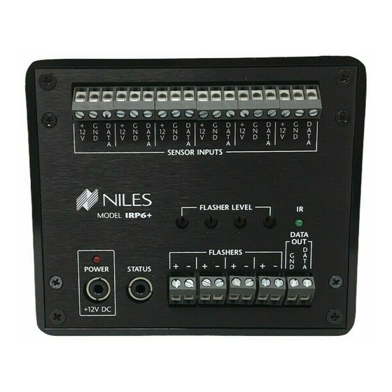
IRP6+
INFRARED EXTENDER SYSTEM—
IR MAIN SYSTEM UNIT
Introduction
An infrared (IR) extender system
The model IRP6+ is an IR Main
enables you to control your IR
System Unit. It is one of three
remote controlled A/V equipment
e l e m e n t s t h a t m a k e u p a n
from a remote location. This
infrared extender system:
enables you to place your A/V com-
1. IR Sensors receive IR commands
ponents out of sight (behind cabi-
from hand-held remote controls and
net doors, in the rear of a room, or
relay the commands to the Main
in a different room) and still conve-
System Unit via a 2-conductor
niently control your equipment.
shielded cable. Generally, sensors
+
MODEL IRP6
FLASHERS
VID
+ -
+ -
+ -
+ -
POWER
STATUS
+12V DC
Remotely Located IR Sensors
Figure 1
IR Remote Controllable Stereo Receiver
DC Power
Supply
Six remotely located IR Sensors are connected to an IRP6+. One IR Flasher, connected to the IRP6+, is transmitting an IR command
to the Receiver's IR sensor. The IRP6+ enables you to connect up to eight Niles IRC-1 Flooding Flashers and up to sixteen Niles
IRC-2 MicroFlashers. The IRP-6+ is powered by plugging into an unswitched AC outlet.
Features and Benefits
The IRP6+ offers a number of
Flasher outputs
improvements over other IR
• Red "Power" L.E.D. enables you to
Extender Main System Units:
test for proper power supply oper-
• Universal system — compatible
ation and shorts between + (posi-
with virtually all brands of A/V
tive) and GND (ground) on your
equipment and remote controls
sensor connections.
(the only exceptions are those
• Green "IR" Test L.E.D. enables you
brands using carrier frequencies
to test for proper operation, inter-
higher than 64kHz).
ference, and for shorts between +
• Exclusive Niles short-circuit protec-
and DATA on your sensor connec-
tion provides for easy installation.
tions.
• Accommodates six IR sensors or
• Built-in "Status" generator broad-
keypads.
casts the amplifier "on/off" power
status over existing IR wiring to
• Provides four low-distortion, high-
provide power status display
current, variable-power Mosfet IR
A
I D E L I T Y
A N D
R C H I T E C T U R E
are placed so that you can easily and
naturally point your remote control
directly at them. Niles offers an array
of easily concealable sensors: wall-
mount, ceiling-mount, surface-
mount and table-top. IR sensors are
the "eyes" of the system.
2. The IR Main System Unit pro-
vides a connection hub for the IR
IR
sensors and the IR flashers and is
DATA
OUT
D
G
A
generally located near the A/V com-
N
T
D
A
ponents. The IR Main System Unit's
level controls and LED indicators
enable you to calibrate and trou-
bleshoot an IR extender system. The
Main System Unit is the "heart" of
an IR extender system.
3. Infrared Flashers transmit the
infrared signals from the IR Main
System Unit to your A/V compo-
nents. Niles manufactures flooding
flashers (model IRC-1) and miniature
"pin-point" flashers (model IRC-2).
IRP6+
when used with other Niles prod-
ucts like the IntelliPad that feature
status display LED's.
• Screw connectors simplify installa-
tion.
• Printed circuit board design
assures high reliability.
• Two year parts and labor warranty.
• Proudly made in the USA.
Niles Audio Corporation
®
®
Advertisement
Table of Contents

Related Manuals for Niles IRP-6


Summary of Contents for Niles IRP-6
-
Page 1: Features And Benefits
Six remotely located IR Sensors are connected to an IRP6+. One IR Flasher, connected to the IRP6+, is transmitting an IR command to the Receiver’s IR sensor. The IRP6+ enables you to connect up to eight Niles IRC-1 Flooding Flashers and up to sixteen Niles IRC-2 MicroFlashers. -
Page 2: Installation Considerations
15 to 20 foot directly at the sensor window. range and a remote with four batter- ies will have a 20 to 30 foot range. 3. Maximum Range between the Remote Control and the Niles IR Sensor is similar to the maximum –... -
Page 3: Troubleshooting Guide
• Power LED Off: Return IRP6+ to 3) 12v DC Power Supply your local Niles dealer for testing Test that the red IRP6+ power LED is on when the wall adapter is plugged 6) Test Sensor Input 1 into an unswitched AC outlet. - Page 4 If you have another IRP6+, exchange with the Red (+) and the Black it and retest the system, otherwise, (DATA) conductors. If you find an return the IRP6+ to your local Niles open, replace or repair the cable as dealer for testing. Troubleshooting Guide continued 33) Test First Sensor Input A) Sunlight.
-
Page 5: Specifications
Niles Audio Corporation 12331 S.W. 130 Street Miami, Florida 33186 Tel: (305) 238-4373 Fax: (305) 238-0185 © 1999 Niles Audio Corporation. All rights reserved. Because Niles constantly strives to improve the quality of its products, Niles reserves the right to change product specifications without notice.
Need help?
Do you have a question about the IRP-6 and is the answer not in the manual?
Questions and answers