Advertisement
Quick Links
Advertisement

Related Manuals for Clevo P150SM-A


Summary of Contents for Clevo P150SM-A
- Page 1 P150SM-A / P151SM-A / P151SM1-A SERVICE MANUAL...
- Page 3 Preface Notebook Computer P150SM-A / P151SM-A / P151SM1-A Service Manual...
- Page 4 Preface Notice The company reserves the right to revise this publication or to change its contents without notice. Information contained herein is for reference only and does not constitute a commitment on the part of the manufacturer or any subsequent ven- dor.
- Page 5 This manual is intended for service personnel who have completed sufficient training to undertake the maintenance and inspection of personal computers. It is organized to allow you to look up basic information for servicing and/or upgrading components of the P150SM-A / P151SM-A / P151SM1-A series notebook PC.
- Page 6 5. This product is intended to be supplied by a Listed Power Unit with an AC Input of 100 - 240V, 50 - 60Hz, DC Output of 19.5V, 9.2A / 19V, 9.5A (180 Watts for P150SM-A & P151SM-A) / 19.5V, 6.15A (120 Watts for P151SM1-A) min- imum AC/DC Adapter.
- Page 7 Preface Instructions for Care and Operation The notebook computer is quite rugged, but it can be damaged. To prevent this, follow these suggestions: Don’t drop it, or expose it to shock. If the computer falls, the case and the components could be damaged. Do not expose the computer Do not place it on an unstable Do not place anything heavy...
- Page 8 Preface Avoid interference. Keep the computer away from high capacity transformers, electric motors, and other strong mag- netic fields. These can hinder proper performance and damage your data. Take care when using peripheral devices. Removal Warning Use only approved brands of Unplug the power cord before When removing any peripherals.
- Page 9 Preface Battery Precautions • Only use batteries designed for this computer. The wrong battery type may explode, leak or damage the computer. • Do not continue to use a battery that has been dropped, or that appears damaged (e.g. bent or twisted) in any way. Even if the computer continues to work with a damaged battery in place, it may cause circuit damage, which may possibly result in fire.
- Page 10 Preface Related Documents You may also need to consult the following manual for additional information: User’s Manual on Disc This describes the notebook PC’s features and the procedures for operating the computer and its ROM-based setup pro- gram. It also describes the installation and operation of the utility programs provided with the notebook PC. System Startup 1.
- Page 11 Preface Contents Introduction ..........1-1 Removing and Installing the Video Card ........2-24 Part Lists ..........A-1 Overview ..................1-1 External Locator - Top View with LCD Panel Open ......1-4 Part List Illustration Location ............A-2 External Locator - Front & Right side Views .........1-5 Top with Fingerprint ..............
- Page 12 Preface Display Port .................. B-18 P150 Click Board ................B-50 HDMI ................... B-19 Power LED Board .................B-51 Lynix Point 1/9 ................B-20 Function LED Board ..............B-52 Lynix Point 2/9 ................B-21 Indicatory LED Board ..............B-53 Lynix Point3/9 ................B-22 P170 2nd HDD Board ..............B-54 Lynix Point 4/9 ................
- Page 13 Chapter 1: Introduction Overview This manual covers the information you need to service or upgrade the P150SM-A / P151SM-A / P151SM1-A series notebook computer. Information about operating the computer (e.g. getting started, and the Setup utility) is in the User’s Manual.
- Page 14 Introduction Specifications Processor Options Security P150SM-A / P151SM-A: Security (Kensington® Type) Lock Slot BIOS Password Intel® Core™ i7 Processor i7-4930MX (3.00GHz) (Factory Option) Fingerprint Reader Module 8MB L3 Cache, 22nm, DDR3L-1600MHz, TDP 57W (Factory Option) TPM 1.2 Storage All Models: Latest Specification Information Intel®...
- Page 15 2GB GDDR5 Video RAM on board One HDMI-Out Port AC Input: 100 - 240V, 50 - 60Hz Microsoft DirectX® 11.1 Compatible One DisplayPort (1.1a) P150SM-A / P151SM-A: Pointing Device One Mini DisplayPort DC Output: 19.5V, 9.2A/ 19V, 9.5A (180W) One S/PDIF Out Jack...
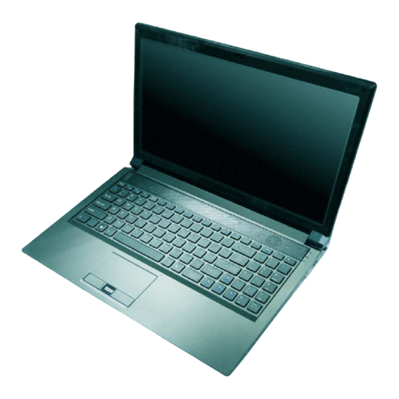
- Page 16 Introduction External Locator - Top View with LCD Panel Open Figure 1 Top View 1. Built-In PC Camera 2. PC Camera LED 3. Built-In Microphone 4. LCD 5. Speakers 6. Power Button 7. LED Lock Indicators 8. LED Status Indicators 9.
- Page 17 Introduction External Locator - Front & Right side Views Figure 2 Front Views 1. LED Power Indicators Front Figure 3 Right Side Views 1. Optical Device Drive Bay 2. Emergency Eject Right Hole 3. Headphone Jack 4. Microphone Jack 5. S/PDIF-Out Jack 6.
- Page 18 Introduction External Locator - Left Side & Rear View Figure 4 Left Side View 1. Mini-IEEE 1394a Port 2. RJ-45 LAN Jack 3. USB 3.0 Ports Left 4. Combined eSATA/ Powered USB 3.0 Port 5. Multi-in-1 Card Reader Figure 5 Rear View 1.
- Page 19 Introduction External Locator - Bottom View Figure 6 Bottom View 1. Vent 2. Component Bay Cover 3. Sub Woofer 4. HDD Bay 5. Battery Overheating To prevent your com- puter from overheating make sure nothing blocks the vent/fan in- takes while the com- puter is in use.
- Page 20 Introduction Mainboard Overview - Top (Key Parts) Figure 7 Mainboard Top Key Parts 1. Platform Controller Hub 2. Audio Codec 3. KBC ITE IT8587 1 - 8 Mainboard Overview - Top (Key Parts)
Need help?
Do you have a question about the P150SM-A and is the answer not in the manual?
Questions and answers