Table of Contents
Advertisement
Quick Links
Advertisement
Table of Contents

Related Manuals for Minarik PCM3


Summary of Contents for Minarik PCM3
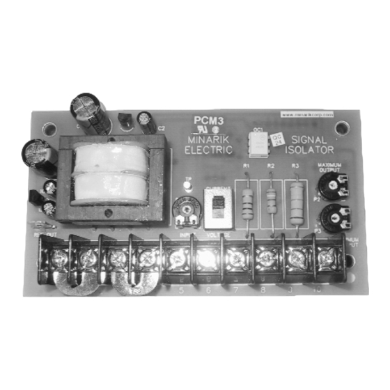
- Page 1 USER’S MANUAL PROCESS CONTROL MODULE PCM3...
- Page 2 All rights reserved. No part of this manual may be reproduced or transmitted in any form without written permission from Minarik Corporation. The information and technical data in this manual are subject to change without notice. Minarik Corporation and its Divisions make no warranty of any kind with respect to this material, including, but not limited to, the implied warranties of its merchantability and fitness for a given purpose.
-
Page 3: Safety Warnings
Safety Warnings SHOCK AVOID HAZARD HEAT ATION • This symbol denotes an important safety tip or warning. PLEASE READ THESE INSTRUCTIONS CAREFULLY before performing any of the procedures contained in this manual. • DO NOT INSTALL, REMOVE, OR REWIRE THIS EQUIPMENT WITH POWER APPLIED. -
Page 4: Table Of Contents
Contents Safety Warnings Specifications Dimensions Introduction Installation Mounting ......... . .4 Wiring . - Page 5 Troubleshooting Certificate of Compliance Unconditional Warranty inside back cover...
- Page 6 Illustrations Figure 1. Process Control Module Dimensions ....2 Figure 2. Screw Terminal Block ......7 Figure 3.
-
Page 7: Specifications
Specifications Power Requirements Line input 115VAC/230 VAC, 50/60 Hz, single phase Input Signal Ranges (input circuit is isolated) Voltage signal, narrow range 0 to +25 VDC Voltage signal, mid range 0 to +120 VDC Voltage signal, wide range 0 to +550 VDC Current signal 1–5 mADC, 4–20 mADC, 10–50 mADC Input Impedance... -
Page 8: Dimensions
Dimensions 4.825 [123] 4.225 [107] MINARIK SIGNAL ELECTRIC ISOLATOR MAXIMUM OUTPUT 2.700 [69] CURRENT 2.150 [55] REF OUT MINIMUM OUTPUT 1.280 [33] MOUNTING HOLE (4 EA) 0.146 [4] DIAMETER 0.250 [6] ALL DIMENSIONS IN INCHES [MILLIMETERS] Figure 1. Process Control Module Dimensions... -
Page 9: Introduction
The maximum PCM3 output voltage is 10 VDC. The PCM3 DC voltage output must be trimmed to not exceed the reference voltage, i.e., the normal voltage drop across the speed adjust potentiometer of the motor speed controller. For Minarik MM20000 series controls, the reference voltage is approximately 3.5 VDC. -
Page 10: Installation
• Prevent loose connections by avoiding excessive vibration of the process control module board. • Mount the PCM3 in either a horizontal or vertical plane. The PCM3 is mounted using 4 ea. 0.25 inch [6mm] standoffs. See Figure 1, page 2 for the physical locations of these standoffs. -
Page 11: Wiring
Installation Wiring Warning Do not install, rewire, or remove this control with input power applied. Failure to heed this warning may result in fire, explosion, or serious injury. This drive is isolated from earth ground. Circuit potentials are at 115 or 230 VAC above ground. To prevent the risk of injury or fatalisty, avoid direct contact with the printed circuit board or with circuit elements. -
Page 12: Shielding Guidelines
Induced voltage can cause unpredictable behavior in any electronic device, including motor controls. As a general rule, Minarik recommends shielding of all conductors. If it is not practical to shield power conductors, Minarik recommends shielding all logic-level leads. If shielding is not practical, the user should twist all logic leads with themselves to minimize induced noise. -
Page 13: Screw Terminal Block
Installation Screw terminal block Connections to Minarik’s PCM3 are made to a screw terminal block. Using a screwdriver, turn the terminal block screw counter- clockwise to open the wire clamp. Insert stripped wire into the wire clamp. Turn the terminal block screw clockwise to clamp the wire. -
Page 14: Ac Line Connections
Connect AC power leads to terminals 1 and 4. When operating on 115VAC, leave the jumper bars installed between terminals 1 and 2 and between 3 and 4 (see Figure 3). This is the PCM3’s default (factory) setting. When operating on 230VAC, remove both jumper bars and place one jumper bar between terminals 2 and 3 (see Figure 4, page 9). -
Page 15: Figure 4. 230Vac Power Connection
Installation MINARIK SIGNAL ELECTRIC ISOLATOR MAXIMUM OUTPUT CURRENT MINIMUM OUTPUT AC POWER 230 VAC INPUT JUMPER BAR INSTALLED BETWEEN TERMINALS 2 & 3 Figure 4. 230VAC Power Connection... -
Page 16: Voltage Follower Connection
Installation Voltage follower connection (1) Set the Current/Voltage Switch to Voltage. (2) Connect the incoming voltage signal leads as shown in Figure 5 below. (3) Connect the negative lead to Terminal 5. (4) If the voltage signal is less than 20VDC, connect the positive lead to Terminal 6. -
Page 17: Current Follower Connection
Installation Current follower connection (1) Set the Current/Voltage Switch to Current. (2) Connect the incoming current signal leads as shown in Figure 6 below. (3) Connect the negative lead to Terminal 5. (4) Connect the positive lead to Terminal 6. MAXIMUM OUTPUT CURRENT... -
Page 18: Leader Signal Generator Connections
Installation Leader signal generator connections The PCM3 can be used as a leader controller in one of two ways. It can provide a floating DC leader voltage input to other PCM3 modules interfacing with standard variable speed drives.It can also drive several variable speed drives directly, provided that their circuit design permits wiring of their speed circuits in common. -
Page 19: Figure 7. Connection - Unidirectional Manual Leader Signal Source
Installation MINARIK SIGNAL ELECTRIC ISOLATOR MAXIMUM OUTPUT CURRENT REF OUT INPUT VOLTAGE MINIMUM OUTPUT 10K OHM SPEED ADJUST POTENTIOMETER Figure 7. Connection – Unidirectional Manual Leader Signal Source... -
Page 20: Output Voltage Connections
Output Voltage Connections Warning Always check the instruction manual supplied with the variable speed drive that will be interfaced with the PCM3 module. The scheme shown for wiring to an external voltage source, as well as the specifications on that input, must be well understood before proceeding. -
Page 21: Figure 8. Connection - Output Voltage
Installation MAXIMUM OUTPUT CURRENT MINIMUM OUTPUT 0 - 10 VDC OUTPUT Figure 8. Connection – Output Voltage... -
Page 22: Armature Voltage Follower
Installation Armature Voltage Follower The PCM3 may be used as an interface to control one motor speed in proportion to that of an independent DC motor. The input signal would be taken from the voltage across the armature of the 'leader' motor, since speed is proportional to this voltage. -
Page 23: Figure 9. Armature Voltage Follower Connections
Installation MINARIK SIGNAL ELECTRIC ISOLATOR MAXIMUM OUTPUT CURRENT REF OUT INPUT VOLTAGE MINIMUM OUTPUT MOTOR 10K OHM SPEED ADJUST POTENTIOMETER MOTOR MM20000 MM20000 SERIES DRIVE SERIES DRIVE (LEADER) (FOLLOWER) Figure 9. Armature Voltage Follower Connections... -
Page 24: Multiple Follower Motors
'leader' PCM3, setting the ratio between two or more of the motor speeds can be accomplished with ratioing pots (Figure 10, page 19). Wire Terminal 10 of the PCM3 to the CW end of the pot. Disconnect that side of the speed pot from its terminal on the follower control. -
Page 25: Figure 10. Multiple Follower Motors Connection
Installation MINARIK SIGNAL ELECTRIC ISOLATOR MAXIMUM OUTPUT CURRENT REF OUT INPUT VOLTAGE MINIMUM OUTPUT 10K OHM MASTER SPEED ADJUST POTENTIOMETER INH2 10K OHM SPEED ADJUST POTENTIOMETER MM20000 SERIES FOLLOWER #1 MOTOR #1 INH2 10K OHM SPEED ADJUST POTENTIOMETER MM20000 SERIES... -
Page 26: Voltage/Current Selector Slide Switch
Voltage/Current Selector Slide Switch See Figure 11 for the Voltage/Current Selector Slide Switch. Set the swtich to VOLTAGE for voltage input mode, otherwise, set it to CURRENT for current input mode. VOLTAGE/CURRENT SELECTOR SLIDE SWITCH MINARIK SIGNAL ELECTRIC ISOLATOR MAXIMUM OUTPUT CURRENT... -
Page 27: Calibration
All adjustments increase with CW rotation, and decrease with CCW rotation. Use a non-metallic screwdriver for calibration. Each trimpot is identified on the printed circuit board. Refer to Figure 12 for trimpot layout. INPUT MINARIK SIGNAL ELECTRIC ISOLATOR MAXIMUM OUTPUT... -
Page 28: Voltage Signal Follower Calibration
DC input voltage to the PCM3. (4) Apply the minimum DC voltage input signal. (5) Adjust MINIMUM OUTPUT trimpot to achieve the desired... -
Page 29: Manual Leader Control
Calibration Manual Leader Control Set the VOLTAGE/CURRENT selector switch to VOLTAGE. Confirm that a 10K ohm leader speed adjust potentiometer has been properly wired between REF OUT (CW) and Terminal 5 (CCW), with its wiper wired to Terminal 6. (1) Set the leader speed adjust potentiometer to maximum (full CW). -
Page 30: Current Signal Follower
DC input current to the PCM3. (4) Apply a 1 mADC signal across Terminals 5 and 6. (5) Adjust MINIMUM OUTPUT trimpot to achieve the desired... -
Page 31: 4-20 Ma Dc Current Signal Input Range
DC input current to the PCM3. (3) Apply a 4 mADC signal across Terminals 5 and 6. (4) Adjust MINIMUM OUTPUT trimpot to achieve the desired... -
Page 32: 10-50 Ma Dc Current Signal Input Range
DC input current to the PCM3. (3) Apply a 10 mA DC signal across Terminals 5 and 6. (4) Adjust MINIMUM OUTPUT trim pot to achieve the desired... -
Page 33: Figure 13. Shunt Resistor Installation
Calibration MINARIK SIGNAL ELECTRIC ISOLATOR MAXIMUM OUTPUT CURRENT MINIMUM OUTPUT SHUNT RESISTOR Figure 13. Shunt Resistor Installation... - Page 34 Before troubleshooting Perform the following steps before starting any procedure in this section: • Disconnect AC line voltage from the PCM3 and variable speed drive. • Check the PCM3 and drive closely for damaged components. • Check that no conductive or other foreign material has become lodged on the printed circuit board.
- Page 35 Suggested Causes Solutions 1. No output voltage 1. Recalibrate the End user’s drive from PCM3 (TB1). PCM3. If there is does not respond to encoder signal still no output send PCM3 to Minarik for repair. 2. Loose connections 2. Check connections...
- Page 36 (TB1) drive does not reach full speed input changes is changing as input changes. Recalibrate the PCM3. IF voltage is still not changing send the drive to Minarik repair. 2. Loose connections 2. Check connections between PCM3 and between TB1 and motor drive.
- Page 37 Certificate of Compliance Minarik Corporation hereby certifies that PCM3 Signal Isolator has been approved to bear the “CE” mark. The PCM3 has been tested to the following test specifications: EN55011:1991 (emissions), and EN50082-1:1992 (immunity) Compliance allows the PCM3 to bear the CE mark.
- Page 38 Certificate of Compliance CE is a machinery directive. Whether or not every component in the OEM’s machinery meets CE, the OEM must still submit its machine for CE approval. Thus, no component must necessarily meet CE within the machine, as long as the OEM takes the necessary steps to guarantee the machine does meet CE.
- Page 39 Notes...
- Page 40 Notes...
- Page 41 Unconditional Warranty A. Warranty - Minarik Corporation (referred to as “the Corporation”) warrants that its products will be free from defects in workmanship and material for two (2) years or 6,000 hours, whichever comes first, from date of shipment thereof. Within this...
- Page 42 901 East Thompson Avenue Glendale, California 91201-2011 Tel.: 1-800-MINARIK (646-2745) Fax: 1-800-394-6334 www.minarikcorp.com Document Number 250-0082, Revision 4 Printed in the U.S.A – 6/02...
Need help?
Do you have a question about the PCM3 and is the answer not in the manual?
Questions and answers