
Related Manuals for Minarik PCM23001A


Summary of Contents for Minarik PCM23001A
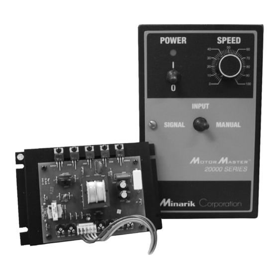
- Page 1 PCM23000 SERIES Models: PCM23001A PCM23401A PCM23411A Signal-Following Speed Controls...
- Page 2 Corporation and its Divisions make no warranty of any kind with respect to this material, including, but not limited to, the implied warranties of its merchantability and fitness for a given purpose. Minarik Corporation and its Divisions assume no responsibility for any errors that may appear in this manual and make no commitment to update or to keep current the information in this manual.
- Page 3 Follow sound maintenance procedures. It is possible for a drive to run at full speed as a result of a component failure. Minarik strongly recommends the installation of a master switch in the main power input to stop the drive in an emergency.
-
Page 4: Table Of Contents
PCM23001A ........ - Page 5 Contents Manual Mode ........20 Signal Follower Mode ......20 Signal with Ratio Output .
- Page 6 Table 5. Corcom® Filters ....... . .43 Table 6. Minarik Filters ........44...
-
Page 7: Specifications
Max. Armature Armature Line Current Voltage Horsepower Model Voltage (Amps DC) Range Range PCM23001A 0 – 90 1/8 – 1 0 – 180 1/4 – 2 PCM23401A 0 – 90 1/8 – 1 0 – 180 1/4 – 2 PCM23411A 0 –... -
Page 8: Dimensions
0.70 [18] 6.30 [160] D508 SCR502 C516 MOV502 T501 4.40 [112] C501 SW501 3.00 [76] IC502 T502 MOV503 C502 IC501 C518 2.30 [58] FOUR MOUNTING SLOTS 0.19 x 3.4 [5 x 9] ALL DIMENSIONS IN INCHES [MM] Figure 1. PCM23001A Dimensions... -
Page 9: Pcm23401A/Pcm23411A
Dimensions PCM23401A/PCM23411A 7.00 [178] FOUR MOUNTING SLOTS 0.19 x 3.4 [5 x 9] ALL DIMENSIONS IN INCHES [MM] Figure 2. PCM23401A/PCM23411A Dimensions... -
Page 10: Installation
Installation Mounting Warning Do not install, rewire, or remove this control with input power applied. Doing so may cause fire or serious injury. Make sure you have read and understood the Safety Warnings before attempting installation. The chassis must be earth grounded. Use a star washer beneath the head of at least one of the mounting screws to penetrate the anodized chassis surface and to reach bare metal. -
Page 11: Wiring
Installation Wiring Warning Do not install, remove, or rewire this equipment with power applied. Failure to heed this warning may result in fire, explo- sion, or serious injury. This drive is isolated from earth ground. Circuit potentials are at 115 or 230 VAC above ground. To prevent the risk of injury or fatality, avoid direct contact with the printed circuit board or with circuit elements. -
Page 12: Shielding Guidelines
Induced voltage can cause unpredictable behavior any electronic device, including motor controls. As a general rule, Minarik recommends shielding of all conductors. If it is not practical to shield power conductors, Minarik recommends shielding all logic-level leads. If shielding of logic level leads is not practical, the user should twist all logic leads with themselves to minimize induced noise. -
Page 13: Line Fuses
Installation Line fuses Protect all Minarik drives with AC line fuses. Use fast acting fuses rated for 250 volts, and approximately 150%–200% of the maximum armature current. Line fusing for PCM20000 series drives Minarik drives require an external fuse for protection. Use fast acting fuses rated for 250 VAC or higher, and approximately 150% of the maximum armature current. -
Page 14: Speed Adjust Potentiometer (Model Pcm23001A Only)
Installation Speed adjust potentiometer (Model PCM23001A only) Warning Be sure that the potentiometer tabs do not make contact with the potentiometer enclosure. Grounding the input will cause damage to the drive. Mount the speed adjust potentiometer through a 0.38 in. (10 mm) hole with the hardware provided (Figure 3). -
Page 15: Pcm23001A Connections
Failure to heed this directive may result in fire or serious injury. Minarik strongly recommends the installation of a master power switch in the voltage input line, as shown in Figure 4, page 12. The switch contacts should be rated at a minimum of 200% of motor nameplate current and 250 volts. -
Page 16: Line Fuse Connections
Refer to the line fuse chart on page 7 for fuse ratings. Motor connections Minarik drives supply motor voltage from A1 and A2 terminals. It is assumed throughout this manual that, when A1 is positive with respect to A2 , the motor will rotate clockwise (CW) while looking at the output shaft protruding from the front of the motor. -
Page 17: Field Output Connections
F1 and F2 when using a permanent mag- net motor. Use 18 AWG wire to connect the field output to a shunt wound motor. Table 2 lists the field output connections. Table 2. PCM23001A Field Output Connections Line Voltage Approximate Connect Motor... -
Page 18: Figure 4. Pcm23001A Connections
Installation Figure 4. PCM23001A Connections... -
Page 19: Current And Voltage Follower
Installation Current and voltage follower The PCM23001A series drives can be configured to follow a grounded (non-isolated) voltage or current signal. To configure the drive to follow a voltage signal, connect the signal leads to the SIGNAL INPUT POS and SIGNAL INPUT NEG terminals, observing proper polarity (see Figure 5). -
Page 20: Figure 6. Current Signal Follower Configuration
Installation D506 D507 MOV501 115 230 SW501 T502 MOV503 CONNECT 1000-OHM RESISTOR ACROSS RSH TERMINALS WHEN USED AS A CURRENT FOLLOWER C518 SO501 4 - 20 mADC SIGNAL INPUT Figure 6. Current Signal Follower Configuration... -
Page 21: Pcm23401A/Pcm23411A Connections
Failure to heed this directive may result in fire or serious injury. Minarik strongly recommends the installation of a master power switch in the voltage input line, as shown in Figure 7 (page 18). The switch contacts should be rated at a minimum of 200% of motor nameplate current and 250 volts. -
Page 22: Motor Connections
Installation Motor connections Minarik drives supply motor voltage from A1 and A2 terminals. It is assumed throughout this manual that, when A1 is positive with respect to A2 , the motor will rotate clockwise (CW) while looking at the output shaft protruding from the front of the motor. If this is opposite of the desired rotation, simply reverse the wiring of A1 and A2 with each other. -
Page 23: Voltage Follower Connections
Installation Table 3. PCM23401A/PCM23411A Field Output Connections Line Voltage Approximate Connect Motor (VAC) Field Voltage (VDC) Field To Terminals 6 (+) and 1 (-) 6 (+) and 7 (-) 6 (+) and 1 (-) 6 (+) and 7 (-) Voltage follower connections The PCM23401A/PCM23411A series drives can be configured to follow a grounded (non-isolated) or non-grounded (isolated) voltage signal. -
Page 24: Figure 7. Pcm23401A/Pcm23411A Connections
Installation 115 VAC INPUT 230 VAC INPUT OR (+) OR (-) 115/230 VAC FIELD SIGNAL INPUT MOTOR INPUT VOLTAGE COILS 0 - 10 VDC NOTE: THE TERMINAL BLOCK IS LOCATED AT THE BOTTOM ON CASED DRIVES. Figure 7. PCM23401A/PCM23411A Connections... -
Page 25: Operation
Operation Warning Dangerous voltages exist on the drive when it is powered. BE ALERT. High voltages can cause serious or fatal injury. Before applying power 1. Verify that no conductive material is present on the printed circuit board. 2. Verify that the AC supply is properly balanced. 3. -
Page 26: Operating Modes
Operation Operating Modes PCM23001A operating modes The PCM23001A can operate in one of three modes,determined by shorting selected pins on mode-select header block SO501. An 18-inch harness and mating plug assembly (Minarik p/n 201-0038) is shipped as part of the PCM23001control. Refer to Figure 8 (page 21) for operating mode connections. -
Page 27: Figure 8. Operating Modes
Operation PCM23001A MANUAL MODE SO501 PCM23001A SIGNAL FOLLOWER MODE SO501 PCM23001A SIGNAL FOLLOWER MODE (RATIO OUTPUT) SO501 Figure 8. Operating Modes... -
Page 28: Pcm23401A/Pcm23411A Operating Modes
Operation PCM23401A/PCM23411A Operating Modes The mode selector switch on the PCM23401A drive, mounted on its cover, provides the option of operating in either MANUAL or SIGNAL mode (see Figure 2, page 3). SIGNAL mode includes the ratio feature described on page 20. Manual/Signal With Ratio Output Mode Selector Connect a switch or relay as shown in Figure 9a (page 23) to select manual or signal with ratio output modes. -
Page 29: Figure 9. Manual/Signal With Ratio Output Mode Select
Operation SO501 (a) MANUAL/SIGNAL WITH RATIOING SELECT SWITCH MANUAL SIGNAL W/ RATIO SO501 (b) MANUAL/SIGNAL ONLY SELECT SWITCH MANUAL ONLY Figure 9. Manual/Signal With Ratio Output Mode Select... -
Page 30: Operating Mode Selector Switch
Operation Operating Mode Selector Switch To enable the selection of an operating mode from either of two possibilities, connect the harness leads to a switch or a relay in accordance with figures 10a, 10b, or 10c (page 25) as your application requires. -
Page 31: Figure 10. Operating Mode Selector Switch Connections
Operation SO501 MANUAL/SIGNAL ONLY ONLY SO501 MANUAL/SIGNAL WITH RATIO OUTPUT (RATIO OUTPUT) SO501 SIGNAL ONLY / SIGNAL WITH RATIO OUTPUT ONLY (RATIO OUTPUT) Figure 10. Operating Mode Selector Switch Connections... -
Page 32: Voltage Select Switches
Operation Voltage Select Switches Warning Change switch settings only when the drive is disconnected from the AC line voltage. Make sure all switches are set to their correct position before applying power. SCR501 D507 D508 SCR502 MOV501 MOV502 C516 T501 115 230 SW501 LINE VOLTAGE... -
Page 33: Line Voltage (Sw501)
Operation Line Voltage (SW501) Prior to applying AC power, ensure that voltage select switches SW501 is set to 115 for 115 VAC line voltage, and 230 for 230 VAC line voltage. Motor Armature Voltage (SW502) Set motor armature voltage switch SW502 to 90 for 90 VDC motor armatures, and 180 for 180 VDC motor armatures. -
Page 34: Calibration
BE ALERT. High voltages can cause serious or fatal injury. PCM23001A Series drives have six user adjustable trimpots: SIG MAX, SIG MIN, MAX SPD, MIN SPD, IR COMP and TORQUE. Recalibrate the trimpots if a lower current motor is used (lower than the rated maximum of the drive). -
Page 35: Figure 12. Calibration Trimpot Layout
Calibration SCR501 D506 D507 D508 MOV501 C516 MOV502 T501 C501 SW501 IC502 T502 MOV503 C502 IC501 SW502 C518 SO501 SIGNAL MAXIMUM TORQUE MAXIMUM SPEED SIGNAL MINIMUM IR COMP MINIMUM SPEED Figure 12. Calibration Trimpot Layout... -
Page 36: Min Spd (Minimum Speed)
Calibration MIN SPD (Minimum Speed) NOTE: Check the MIN and MAX trimpot setting after recalibrating to verify that the motor runs at the desired minimum speed. The MIN trimpot setting determines the motor speed when the speed adjust potentiometer is turned full CCW. It is operational only in MANUAL mode and is factory set to zero speed. -
Page 37: Sig Min (Signal Minimum)
Calibration SIG MIN (Signal Minimum) NOTE: SIG MIN is operative only when the control is in SIGNAL or SIGNAL WITH RATIO OUTPUT mode. The SIG MIN trimpot establishes the motor speed obtained in response to the minimum input signal. To calibrate the SIG MIN pot, apply the minimum signal. Adjust the SIG MIN trimpot until the motor runs at the desired speed or is just at the threshold of rotation. -
Page 38: Torque
If you intend to operate beyond the rating, contact your Minarik representative for assistance. The TORQUE trimpot setting determines the maximum torque for accelerating and driving the motor. Use the following procedure to calibrate the TORQUE setting: 1. -
Page 39: Ir Comp (Ir Compensation)
Calibration IR COMP (IR Compensation) The IR COMP trimpot setting determines the degree to which motor speed is held constant as the motor load changes. It is factory set for optimum motor regulation. To calibrate IR COMP (exact calibration): 1. Turn the IR COMP trimpot full CCW. 2. -
Page 40: Figure 13. Pcm23001A Ir Comp And Torque Trimpot Settings
180 VDC 5 AMP RATING 5 AMP RATING IR COMP TORQUE IR COMP TORQUE 1 HORSEPOWER 2 HORSEPOWER 1750 RPM 1750 RPM 90 VDC 180 VDC 10 AMP RATING 9.2 AMP RATING Figure 13. PCM23001A IR Comp and Torque Trimpot Settings... -
Page 41: Troubleshooting
5. Verify that there are no short circuits or grounded connections. 6. Check that the drive’s rated armature outputs are consistent with the motor ratings. For additional assistance, contact your local Minarik distributor, or the factory direct: 1-800-MINARIK (646-2745) or Fax: 1-800-394-6334... - Page 42 “jams”. See page 32 for information on adjusting the TORQUE trimpot. 4. Field circuit is open. 4. Send in drive to Minarik repair department.
-
Page 43: Connect Motor Field To
Troubleshooting Problem Possible Suggested Causes Solutions Line fuse does not 1. Speed adjust pot or 1. Increase speed adjust blow, but the motor signal input is set to pot or signal input does not run zero speed. setting. 2. Speed adjust pot or 2. - Page 44 Troubleshooting Problem Possible Suggested Causes Solutions Motor runs too slow 1. MIN SPD and MAX 1. Calibrate MIN SPD or too fast SPD are not calibrated. and MAX SPD. Motor will not reach 1. MAX SPD setting is too 1. Increase MAX SPD the desired speed.
-
Page 45: Figure 14. Pcm23001A Schematic
SIGNAL INPUT P501 P502 FIELD OUTPUT 470K LINE INPUT R531 .047 100K .01/5W MOV503 1.5M IC501 DST-2-20 TORQUE 78L05 SPDT V275LA4 LIMIT P505 C502 MOV501 MIN SPD 100K V275LA20A C501 100K IR COMP IC502 P506 79L05 Figure 14. PCM23001A Schematic... -
Page 46: Figure 15. Pcm23401A/Pcm23411A Schematic
Figure 15. PCM23401A/PCM23411A Schematic... -
Page 47: Replacement Parts
Troubleshooting Replacement Parts Replacement parts are available from Minarik Corporation and its distributors for this drive series. Table 4. Replacement Parts Model No. Symbol Description Minarik P/N PCM23001A Header Block Harness 201-0038 Fuse Kit (1 - 5A) 050-0066 Fuse Kit (5 - 15A) -
Page 48: Certificate Of Compliance
The PCM20000 series has been tested to the following test specifications: EN55011:1991 (emissions), and EN50082-1:1992 (immunity) Compliance allows Minarik’s PCM20000 series to bear the CE mark. The end user, as described herein, falls into one of two categories: 1. The Consumer will deploy a stand-alone unit as an integral, yet external, portion of the machine he/she is operating. -
Page 49: Exhibit A
In addition to EMI/RFI safeguards inherent in the PCM20000 series’ design, external filtering is required. Minarik requires the Corcom® filters listed in Table 5. If the exact filter is not available, the specifications are as follows: L = (1.73 + 0.03) milliHenries. -
Page 50: Table 6. Minarik Filters
CE Compliance If the end-user is not using a CE-approved motor, a second filter on the output, Minarik’s CEXXMM, must be used. XX = rated current of the filter. The CE20MM is a Real-Pole Balanced-Pi 3-pole filter. If the exact filter is not available, the specifications are as follows: L &... - Page 51 CE Compliance The OEM has this liberty because CE is a machinery directive. Whether or not every component in the OEM’s machinery meets CE, the OEM must still submit his machine for CE approval. Thus, no component must necessarily meet CE within the machine, as long as the OEM takes the necessary steps to guarantee the machine does meet CE.
- Page 52 NOTES...
- Page 53 NOTES...
- Page 54 NOTES...
-
Page 55: Unconditional Warranty
Unconditional Warranty A. Warranty Minarik Corporation (referred to as "the Corporation") warrants that its products will be free from defects in workmanship and material for twelve (12) months or 3,000 hours, whichever comes first, from date of manufacture thereof. Within this warranty... - Page 56 901 East Thompson Avenue Glendale, California 91201-2011 Tel.: 1-800-MINARIK (646-2745) Fax: 1-800-394-6334 www.minarikcorp.com Document Number 250-0104, Revision 7 Printed in the U.S.A – September 2002...
Need help?
Do you have a question about the PCM23001A and is the answer not in the manual?
Questions and answers