Table of Contents
Advertisement
Quick Links
Advertisement
Table of Contents

Related Manuals for RetroSound Technophonic


Summary of Contents for RetroSound Technophonic
- Page 1 Technophonic 5-Channel Amplifier USER’S MANUAL MODERN SOUND FOR YOUR CLASSIC...
-
Page 2: Table Of Contents
Table of Contents Welcome ..........2 What’s in the Box ........3 Precautions ........4 Mounting the Amplifier ......6 Power and Ground Connections ....... 7 Fuses ..........9 Wiring: RCA | 5 Channel ......10 Wiring: Speaker Connections | 5 Channel .... 11 Wiring: Speaker Connections | Bridged .... -
Page 3: Welcome
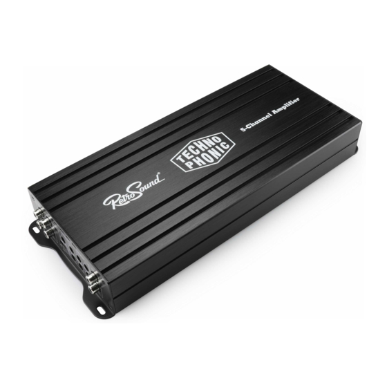
Welcome Thank you for purchasing a RetroSound Technophonic ® 5-channel amplifier. General Features • 5-channel amplifier • Full-range Class D digital circuitry • 65-watt RMS x 4 channels full-range @ 4 ohms (95-watts RMS x 4 @ 2 ohms) •... -
Page 4: What's In The Box
What’s in the box The items shown below are packaged with your Techno- phonic amplifier. Technophonic Amplifier Hex Wrench (x2) Remote Gain Control Large Metal Screw (x4) Small Metal Screw (x4) (for mounting the amplifier) (for mounting the Remote Gain Control) -
Page 5: Precautions
Precautions PLEASE OBSERVE THESE PRECAUTIONS WHEN INSTALLING AND USING THIS UNIT: This user’s manual does not cover all possible installation scenarios. Please be sure to follow the instructions carefully while attempting instal- lation. If you feel you cannot install this unit yourself, consult with a local car audio professional. - Page 6 Precautions • Do not disassemble or modify the unit or attempt to repair it yourself. If your unit is not working properly please consult your dealer or Retro Manufacturing, LLC. • This unit is not designed for a marine environment. Please do not use the unit where it will be exposed to moisture or excessive dust.
-
Page 7: Mounting The Amplifier
Mounting The Amplifier Leave 2” to 5” of clearance for proper airflow. It is best to mount the amplifier in a location that allows air to freely circulate around it and allows access to the end panel controls for adjustments. Although both thermal and overload protection are built in, if the amplifier overheats it will reduce its power output to maintain operation. -
Page 8: Power And Ground Connections
Power and Ground Connections Electrical System Test The Technophonic amplifier is designed to work within a range of 12 volts to 14.4 volts DC. Before connecting any wiring, use a multi-meter to test the vehicle’s electrical system for adequate power supply. First, check the voltage at the battery with the ignition in the off position. - Page 9 Power and Ground Connections Constant 12 volt (+) Battery Wire The constant 12 volt (+) battery wire (not included) should be wired directly to the vehicle’s positive (+) battery terminal using 8 to 4 gauge primary wire de- pending on run length. Start at the vehicle’s battery, and run the cable back to the amplifier.
-
Page 10: Fuses
The fuses included with the Technophonic amplifier are to replace the internal fuses and only protect the amplifier itself in case of short-circuit. To replace the internal fuses, remove the panel on the bottom of the amplifier and replace the blown fuses as needed. -
Page 11: Wiring: Rca | 5 Channel
2 on the amplifier. The rear RCA outputs connect to channels 3 and 4. The RCA outputs for the subwoofer connect to both inputs on channel 5 of the Technophonic amplifier. For radios with only 2 or 4 outputs use the mode select switch (see page 15). -
Page 12: Wiring: Speaker Connections | 5 Channel
Wiring: Speaker Connections | 5 Channel For five speaker systems, connect the speakers to channels 1-5. Strip 1/2 inch (12 mm) of insulation from the end of each wire and twist the ends. Back out the set screws 3/4 of the way out and insert each wire firmly and completely, leaving no exposed wire. -
Page 13: Wiring: Speaker Connections | Bridged
Connect the second bridged speaker to the positive terminal on channel 3 and the negative terminal on channel 4. The subwoofer connects to channel both 5 inputs. The Technophonic amplifier is 2 ohm and 4 ohm stable. Left Front Speaker... -
Page 14: Controls
Controls A. High Pass Filter (HPF) The HPF (adjustable between 40Hz and 400Hz) filters out high frequencies below the designated setting on the amplifier while attenuating frequencies above that setting. B. Low Pass Filter (LPF) The LPF (adjustable between 50Hz and 250Hz) filters out low frequencies above the designated setting on the amplifier while attenuating frequencies below that setting. - Page 15 Controls E. Gain Controls This control is used to match the input sensitivity of the amplifier to the radio. The Gain Control is not a volume control. Use the source unit (radio) to control system volume. Use these steps to properly set all three gains: 1.
-
Page 16: Mode Select Switch
Mode Select Switch The Technophonic amp can be set to two, four or five channel mode to match the number of outputs the connected radio has. When set to two or four channel modes the amplifier will create the additional outputs internally so all five outputs can be used. -
Page 17: Troubleshooting
Troubleshooting Problem Solution • Check to ensure that the Battery (+)(12 volt constant) wire has 12 to 14.4 volts. Green Power LED • Check to ensure that the amplifier does not turn on turn-on lead has 12 volts. • Check the fuses at bottom of the amplifier. -
Page 18: Specifications
Specifications Amplifier Amplifier Full-Range Output Power ....65 Watts x 4 channels RMS @ 4 ohms Subwoofer Power Output ......225 Watts x 1 channel @ 4 ohms Full-Range Output Power ....95 Watts x 4 channels RMS @ 2 ohms Subwoofer Power Output ......330 Watts x 1 channel @ 2 ohms Signal to Noise Ratio ................>95dB Input Sensitivity .............. -
Page 19: Warranty
ITEM ITEM WARRANTY WARRANTY Technophonic One (1) Year During the "Parts" warranty period, there will be no charge for parts. You must mail in your unit during the warranty period at your expense. This warranty only applies to products purchased directly from Retro Manufacturing or an authorized dealer. This warranty is extended only to the original purchaser of a new product that was not sold "as is."... - Page 20 7470 Commercial Way | Henderson, NV 89011 help.retromanufacturing.com MODERN SOUND FOR YOUR CLASSIC Published: 02/10/2023 | ©2023 Retro Manufacturing, LLC www.retromanufacturing.co m...
Need help?
Do you have a question about the Technophonic and is the answer not in the manual?
Questions and answers