
Related Manuals for Danelec DM700 ECDIS


Summary of Contents for Danelec DM700 ECDIS
- Page 1 Installation Manual for DM700 ECDIS Document Number MAN11805 Version Number Date December 2016 P/N (hard copy) 9303970-10...
-
Page 2: Revision Record
Installation manual for DM700 ECDIS Copyright Danelec Marine A/S Revision record Version Date Description 2016-12-09 Initial version of document MAN11805-10 Page 2/67... -
Page 3: Table Of Contents
Installation manual for DM700 ECDIS Copyright Danelec Marine A/S Contents REVISION RECORD ......................2 SCOPE AND PURPOSE ..................6 References ........................ 6 Terms and Abbreviations ..................6 SYSTEM OVERVIEW ....................7 Main Unit ........................8 2.1.1 DPU ........................8 2.1.2 USB hardware key ..................... - Page 4 Installation manual for DM700 ECDIS Copyright Danelec Marine A/S CONFIGURATION OF THE ECDIS SOFTWARE ..........30 Main Screen ......................30 Main Menu ......................31 Service Technician Access ..................31 Sensors (Input/Output) .................... 32 6.4.1 Creating a new sensor ..................32 6.4.2...
- Page 5 Installation manual for DM700 ECDIS Copyright Danelec Marine A/S INSTALLATION PLAN ................... 57 COMMISSIONING ....................59 MAINTENANCE SCHEDULE ................. 59 LIST OF SPARE PARTS ..................59 APPENDIX A - INSTALLATION DRAWINGS FOR MAIN UNIT ......60 APPENDIX B - INSTALLATION DRAWINGS FOR EK 03-001 KEYBOARD ..62 APPENDIX C - INSTALLATION DRAWINGS FOR CORTRON KEYBOARD ..
-
Page 6: Scope And Purpose
Copyright Danelec Marine A/S Scope and purpose Installation manual for DM700 ECDIS. References DBS11425 User manual for Danelec Marine ECDIS Software P/N 9303396 MAN11804 User manual for DM700 ECDIS hardware P/N 9303969 Terms and Abbreviations M2.SATA-SSD SATA Solid State Disk with M2 interface... -
Page 7: System Overview
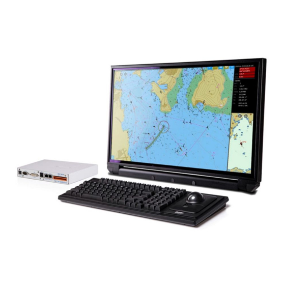
Installation manual for DM700 ECDIS Copyright Danelec Marine A/S System overview A DM700 ECDIS system consists of the following parts: Monitor Keyboard Power COM1 USB 4 ECDIS DM700 DPU USB 2 HW-KEY 2 x IEC 3 x IEC Ethernet 61162-2... -
Page 8: Main Unit
2.1.2 USB hardware key The USB hardware key contains the keys needed for enabling access to charts. The USB hardware key is located under the service cover, on the DM700 ECDIS DPU. 2.2 Monitor The monitor must be installed on a table top using the monitor hinge, or be flush mounted in the console. -
Page 9: Keyboard
Some of the most important functions on the ECDIS are also located on the [F1] - [F10] function- key (see DBS11425 “User Manual for Danelec Marine ECDIS software”). A sticker showing symbols for the hot-key functionality is mounted on the keyboard. -
Page 10: Ecdis Cluster
A complete ECDIS installation will in most cases consist of a number of systems (a cluster). The DM700 ECDIS can be connected directly together if the cluster contains only two systems. The DM700 ECDIS’s must be connected using an Ethernet switch if the cluster contains more than two systems. - Page 11 Installation manual for DM700 ECDIS Copyright Danelec Marine A/S The DM700 ECDIS and DM800 ECDIS G2 can be combined in a cluster. It will not be possible have redundant network connections if the DM800 ECDIS G2 and DM700 ECDIS are used...
-
Page 12: Specification Of Cables For The Ecdis Cluster
1, 2 or 3 Backup ECDIS computers (DM700 ECDIS or DM800 ECDIS G2) 1, 2 or 3 Route planning stations (DM700 ECDIS or DM800 ECDIS G2) (The maximum cluster size consists of 4 x DM700 ECDIS or DM800 ECDIS G2) 2.4.1 Specification of cables for the ECDIS cluster As a minimum, CAT5e STP cables must be used for the ECDIS cluster. -
Page 13: Installation
Installation manual for DM700 ECDIS Copyright Danelec Marine A/S Installation The installation must be carefully planned and will depend on the vessel. Section 4 “Recommended standard configuration” shows the standard configuration. It is highly recommended that the standard configuration is used as a starting point. -
Page 14: Installation Kit
Installation manual for DM700 ECDIS Copyright Danelec Marine A/S 3.2 Installation kit An installation kit P/N 2303936 is supplied with each DM700 ECDIS. It contains the follow parts: Item Usage Support for USB For securing the cable to the keyboard... -
Page 15: Power Requirements
An installation label, showing the Installation ID for the main unit, is located on the mounting foot and mounting ‘angle and plate’. This is the main identification for the system and must not be removed from the installation, for example following repair of the DM700 ECDIS DPU. MAN11805-10... -
Page 16: Recommended Standard Configuration
Installation manual for DM700 ECDIS Copyright Danelec Marine A/S Recommended standard configuration Please note the following when planning the installation: Each DPU contains a computer for the ECDIS software and communication I/O Interface. When connected properly, each I/O Interface in the cluster is able to send data to any ECDIS computer in the cluster. -
Page 17: System Configuration
1. Connect DC Power from the Wave monitor 2. Apply AC power to the Wave monitor 3. If the “POWER”-LED on the front of the DM700 ECDIS is not lit, press the Power button on the Monitor HMI briefly. MAN11805-10... -
Page 18: Initial Configuration Of The Master Ecdis
Installation manual for DM700 ECDIS Copyright Danelec Marine A/S 5.2 Initial configuration of the Master ECDIS After the startup sequence, an ECDIS from the factory will show the configuration wizard. Click on [Next] to continue. MAN11805-10 Page 18/67... -
Page 19: Configuration Of Monitor Type
Installation manual for DM700 ECDIS Copyright Danelec Marine A/S 5.2.1 Configuration of monitor type Select the monitor to be used. The wizard will automatically try to detect the monitor connected. Select the correct monitor in the drop-down list, and click on [Apply]. -
Page 20: Configuration Of Alert Buzzer
Installation manual for DM700 ECDIS Copyright Danelec Marine A/S The border of the image should have 3 white lines all the way around. Not OK: Click on [Next] to continue. 5.2.2 Configuration of alert buzzer Select which alert buzzer to use. -
Page 21: Configuration Of Cluster Size
Installation manual for DM700 ECDIS Copyright Danelec Marine A/S 5.2.4 Configuration of cluster size Enter the size of the cluster - i.e. how many ECDIS’s are to be installed on the vessel. Press [Next] to continue. Select node ID and the role of this ECDIS. This information must appear on the installation plan for the vessel. -
Page 22: Initial Configuration Of Network Port
Installation manual for DM700 ECDIS Copyright Danelec Marine A/S 5.2.5 Initial configuration of network port Ethernet port ‘LAN 1’ is used for connecting the cluster together, while Ethernet port ‘LAN2’ is for general purpose. It is possible to use the external port ‘LAN2’ for the following features: 1. -
Page 23: Initial Configuration Of External Equipment
Installation manual for DM700 ECDIS Copyright Danelec Marine A/S 5.2.6 Initial configuration of external equipment Transmission of images via IEC61162-450 and synchronization of charts from a NavBox are configured here. It requires the external network interface to be enabled to work correctly. -
Page 24: Configuration Of Local Serial Ports
Installation manual for DM700 ECDIS Copyright Danelec Marine A/S 5.2.7 Configuration of local serial ports For each utilized serial line configure the following: 1. Enable the port. 2. Fill in “Name” with text that identifies the sensor. 3. The communication parameters for the serial interface are set according to general accepted standards but can be changed if needed. -
Page 25: Saving The Initial Configuration
Installation manual for DM700 ECDIS Copyright Danelec Marine A/S 5.2.8 Saving the initial configuration Click [Apply] to save the initial configuration When finished, all tasks will be marked with a green check mark. Click on [Next] to continue. MAN11805-10 Page 25/67... -
Page 26: Finalizing The Configuration
Installation manual for DM700 ECDIS Copyright Danelec Marine A/S A dialog box for how to utilize ports on other ECDIS’s will be displayed, but leave this ECDIS for now and configure the remaining ECDIS’s. 5.3 Finalizing the configuration The final configuration requires all ECDIS’s to have an initial configuration, to be operative and to be connected to the cluster. - Page 27 Installation manual for DM700 ECDIS Copyright Danelec Marine A/S Check that all other ECDIS’s are present. If this is not the case, check that all ECDIS’s have an initial configuration, are operative and connected to the cluster. Only ports from other DM700 ECDIS or DM800 ECDIS G2 can be shown and used.
-
Page 28: Configuration Of Usb Hardware Key
It is the USERPERMIT of this hardware key which will be used for the whole cluster. We recommend using the hardware key inserted in node 1 (which has the ECDIS master role) as primary hardware key. Only DM700 ECDIS and DM800 ECDIS G2 can be connected in the cluster. - Page 29 USERPERMIT as used when ordering the charts. This will ensure correct operation during charts import. You can only modify the role of the local hardware key. Consult MAN11804 “User manual for DM700 ECDIS hardware” for further details. Click on [Finish] and the ECDIS Software will start.
-
Page 30: Configuration Of The Ecdis Software
Specifying precise positions of sensors onboard The following step must also be performed, but may be synchronized between nodes. (Refer to DBS11425 “User manual for Danelec Marine ECDIS software” for description of how to synchronize between ECDIS’s) 2. Specifying vessel performance characteristics 3. -
Page 31: Main Menu
Installation manual for DM700 ECDIS Copyright Danelec Marine A/S 6.2 Main Menu “Main Menu” provides access to all ECDIS functions and settings. 1. Press the Main Menu button in the lower-left corner of the Chart View. 2. The Main Menu panel opens where you can access ECDIS functions and settings. -
Page 32: Sensors (Input/Output)
Installation manual for DM700 ECDIS Copyright Danelec Marine A/S 6.4 Sensors (Input/Output) Data about the own vessel position, course, speed and other vessel movement characteristics, as well as the data about the surrounding conditions is received using special navigation devices such as positioning systems, gyro devices, and other sensors. - Page 33 Installation manual for DM700 ECDIS Copyright Danelec Marine A/S 4. The sensor is added to the panel and indicators of its main NMEA sentences appear in the Sensors panel. 5. Select the sensor to open the sensor parameters panel. 6. Set new values for sensor parameters.
-
Page 34: Line Monitor
Installation manual for DM700 ECDIS Copyright Danelec Marine A/S A sensor has the following parameters: a) Priority – Priority of the sensor if several sensors of the same type are registered; if the sensor with the highest priority is lost, the sensor with the next priority is used instead;... -
Page 35: Deleting A Sensor
Installation manual for DM700 ECDIS Copyright Danelec Marine A/S 7. To close the Line monitor panel, press the [Close] button: the panel is closed. 6.4.3 Deleting a sensor 1. Go to Main Menu Settings Vessel Sensors: the Sensors panel opens. - Page 36 Installation manual for DM700 ECDIS Copyright Danelec Marine A/S Sensor Messages Image Radar targets TTM TLL TLB TTD TXT Alert ALR ACK TXT ALF ACM ALC ARC Autopilot NAVTEX NRX NRM TXT BNWAS MAN11805-10 Page 36/67...
-
Page 37: Vessel Particulars Setup
Installation manual for DM700 ECDIS Copyright Danelec Marine A/S 6.5 Vessel Particulars Setup Configuring operating parameters of the own ship is very important for the correct functioning of the system. The own ship parameters are configured in the Main Menu Settings Vessel ... -
Page 38: Static Ship And Voyage Data
Certain ECDIS functions, for example manual observation, require additional information about measuring devices onboard the own vessel including their precise position, angle and distance errors. The complete description can be found in DBS11425”User manual for Danelec Marine ECDIS software”. 6.6 Static Ship and Voyage Data The following parameters must be configured for the own vessel: ECDIS talker ID, MMSI, ship name, call sign, IMO number, ship static data, and voyage static data. - Page 39 Installation manual for DM700 ECDIS Copyright Danelec Marine A/S 2. Enter parameters in corresponding fields. 3. To apply the parameters, press the [Apply] button. 4. You are prompted for the MASTER password. (use the SERVICE password) 5. To apply, go to the Main Menu Settings Vessel Vessel particulars Ship static data 6.
-
Page 40: Initial Data Installation
Chart and permit installation is usually performed by the end users, but is it good practice to help the users by performing the initial chart and permit installation. Please refer to DBS11425“User manual for Danelec Marine ECDIS software” for description and explanation of how to import IHO-certificate, permit and ENC chart data. -
Page 41: Advanced Configuration
Installation manual for DM700 ECDIS Copyright Danelec Marine A/S Advanced configuration Warning: Do not attempt to enable these functionalities unless you are familiar with IP networks. Configuration of access to external data network Ethernet port ‘LAN2’ on the DPU may be used to access a local area IP network or to access a general purpose IP network on the vessel. -
Page 42: Configuration Of External Equipment
Installation manual for DM700 ECDIS Copyright Danelec Marine A/S 7.2 Configuration of External Equipment Two types of external equipment can be configured on this page: 1. IEC61162-450 image output to VDR (or similar equipment) 2. Connection to NavBox for chart updates... -
Page 43: Iec61162-450 Image Output
Installation manual for DM700 ECDIS Copyright Danelec Marine A/S 7.2.1 IEC61162-450 Image output The ECDIS supports transmitting a screenshot of the display to a VDR every 15 seconds, in accordance with IEC61996-1 Ed.2 Appendix E, and the chart information in accordance with IEC61996-1 Ed.2 Appendix G. -
Page 44: Navbox Chart Update
The shared path of chart database must be configured for this feature to work. Replace the “????” with the IP of the NavBox. E.g.: \\192.168.1.2\enc Please refer to DBS11425 “User manual for Danelec Marine ECDIS software” for details of how to use the NavBox from the ECDIS software. -
Page 45: Configuration Of Virtual Data Lines Via Tcp/Ip
Installation manual for DM700 ECDIS Copyright Danelec Marine A/S 7.3 Configuration of virtual data lines via TCP/IP Data may be received from sensors via TCP/IP using the Ethernet port on the DPU The panel for setting up local ports must be open. Click on [add …] to create a virtual line for receiving data. -
Page 46: Advanced Local Port Configuration
Installation manual for DM700 ECDIS Copyright Danelec Marine A/S Advanced local port configuration The local ports are one-way ports. They are either receiving (RX) or transmitting (TX) ports. If it is required to use both RX and TX for the same device, two ports must be used and merged (linked) to one port. -
Page 47: Service Menu
Installation manual for DM700 ECDIS Copyright Danelec Marine A/S Service Menu The ECDIS hardware can be reconfigured if needed. Service menu is entered from the ECDIS software. To open the panel, do the following: 1. Open the Main Menu by clicking the menu icon in the bottom left corner: 2. -
Page 48: Service Panel
View system logs: Displays the system log files View manuals: Displays the manuals. Software update: Consult MAN11804 “User manual for DM700 ECDIS hardware” System configuration restore: Restores all configuration files from previous backup file, or dump for support file. (System will restart) ... -
Page 49: Replacement Of Defective Dpu
Installation manual for DM700 ECDIS Copyright Danelec Marine A/S System cleanup: Removes old log files and perform disk cleanup Remove all configurations (not charts): Removes all configuration files, system log files and logbook files to make a virgin system. Installed charts are not removed. (System will restart) ... -
Page 50: Dump For Support
Installation manual for DM700 ECDIS Copyright Danelec Marine A/S 8.3 Dump for support Utilize this feature if help for troubleshooting is needed from Danelec Marine. “Dump for support” can be started from a number of places: 8.3.1 From within the ECDIS software 1. -
Page 51: Re-Installation Of Ecdis
The DM700 ECDIS includes a recovery boot system. This can be used to reinstall the ECDIS to factory image. 1. Power the DM700 ECDIS off and on again (use the power button on the Monitor HMI). As soon as “beeps” are heard from the DPU or text appears on the monitor, press [F5] repeatedly and the “boot menu”... -
Page 52: Install Ecdis
Installation manual for DM700 ECDIS Copyright Danelec Marine A/S 9.1 Install ECDIS Boot the system using recovery boot system as described in section 9 “Re-installation of ECDIS”. Click on “Install ECDIS version x.xx” Confirm the installation by typing “install” Wait for the installation to finish. You can follow the progress in the info-window. - Page 53 Installation manual for DM700 ECDIS Copyright Danelec Marine A/S After the installation is complete, the following message is shown: Click on “Yes” The ECDIS will reboot and revert to the factory installation (no charts will have been preinstalled). Continue from section 5 ”System configuration”...
-
Page 54: Detailed Specification Of The Iec 61162-450 Interface
Installation manual for DM700 ECDIS Copyright Danelec Marine A/S 10 Detailed specification of the IEC 61162-450 interface IEC 61162-450 data is only supported on the external network interfaces (LAN2) 10.1 Maximum data rate The maximum output rate for IEC 61162-450 image data is 2MB/s. -
Page 55: Specification For Interface, Connectors And Cables
Installation manual for DM700 ECDIS Copyright Danelec Marine A/S 10.6 Specification for Interface, connectors and cables Interface Max network Connector Cable category, segment link assignment minimum distance The 8-way modular 1000BASE-T 100m IEC 60603-7-7, 8- CAT5 STP connector specified in IEC IEEE 802.3... -
Page 56: Minimum Requirements For Ethernet Switch
11 Minimum requirements for Ethernet switch The following described the minimum requirements for an Ethernet switch used to connect the external network of the DM700 ECDIS to a VDR, Navbox or other 3 party equipment. Interface must be: 1000BASE-T IEEE 802.3 Clauses 40 (802.3ab) -
Page 57: Installation Plan
Installation manual for DM700 ECDIS Copyright Danelec Marine A/S 12 Installation plan Monitor Keyboard For chart update USB1 USB2 USB3 USB4 COM1 12VDC DPU 700-01 LAN1 LAN2 SI00 SI01 SI02 SI03 SI04 Boundary for ECDIS main cabinet ECDIS Cluster Sensor IEC... - Page 58 Installation manual for DM700 ECDIS Copyright Danelec Marine A/S 1) Connect the USB cable attached to keyboard to USB 4 and secure with “Support for USB”. 2) Use the cable (DB9-DB)) supplied in the installation kit. 3) Use the DVI cable supplied in the installation kit.
-
Page 59: Commissioning
Installation manual for DM700 ECDIS Copyright Danelec Marine A/S 13 Commissioning Perform the installation performance test (IPT) for the Danelec Marine DM700 ECDIS. The installation performance test procedure can be downloaded from http://www.danelec- marine.com. 14 Maintenance schedule Every year (recommended): Perform the annual performance test (APT). The annual performance test procedure can be downloaded from http://www.danelec-marine.com. -
Page 60: Appendix A - Installation Drawings For Main Unit
Installation manual for DM700 ECDIS Copyright Danelec Marine A/S 16 Appendix A - Installation drawings for main unit MAN11805-10 Page 60/67... - Page 61 Installation manual for DM700 ECDIS Copyright Danelec Marine A/S MAN11805-10 Page 61/67...
-
Page 62: Appendix B - Installation Drawings For Ek 03-001 Keyboard
Installation manual for DM700 ECDIS Copyright Danelec Marine A/S 17 Appendix B - Installation drawings for EK 03-001 keyboard MAN11805-10 Page 62/67... - Page 63 Installation manual for DM700 ECDIS Copyright Danelec Marine A/S MAN11805-10 Page 63/67...
-
Page 64: Appendix C - Installation Drawings For Cortron Keyboard
Installation manual for DM700 ECDIS Copyright Danelec Marine A/S 18 Appendix C - Installation drawings for Cortron keyboard MAN11805-10 Page 64/67... - Page 65 Installation manual for DM700 ECDIS Copyright Danelec Marine A/S MAN11805-10 Page 65/67...
- Page 66 Installation manual for DM700 ECDIS Copyright Danelec Marine A/S MAN11805-10 Page 66/67...
- Page 67 Installation manual for DM700 ECDIS Copyright Danelec Marine A/S MAN11805-10 Page 67/67...
Need help?
Do you have a question about the DM700 ECDIS and is the answer not in the manual?
Questions and answers