
Subscribe to Our Youtube Channel
Related Manuals for Danelec DM700 ECDIS


Summary of Contents for Danelec DM700 ECDIS
- Page 1 User Manual for DM700 ECDIS hardware Document Number MAN11804 Version Number Date December 2016 P/N (hard copy) 9303969-10...
-
Page 2: Revision Record
User manual for DM700 ECDIS hardware Copyright Danelec Marine A/S Revision record Version Date Description 2016-12-02 Initial version of document MAN11804-10 Page 2/30... -
Page 3: Table Of Contents
Control of Monitor ....................13 Nominal viewing distance ..................13 SELF-TEST......................14 Buzzer in monitor HMI ..................... 14 Test of monitor ......................14 DM700 ECDIS DATA PROCESSING UNIT (DPU 700-01) ........15 Power ........................15 Status LED’s ......................16 6.2.1 Status LED ....................... 16 SYSTEM MANAGEMENT MENU ................ - Page 4 User manual for DM700 ECDIS hardware Copyright Danelec Marine A/S 7.3.1 Stand-alone configuration ................21 7.3.2 Cluster configuration ..................21 Install software update .................... 21 Software Version ..................... 22 Verification of System Software Version ..............23 HARDWARE ERRORS ..................24 List of hardware alerts .....................
-
Page 5: Scope And Purpose
User manual for DM700 ECDIS hardware Copyright Danelec Marine A/S Scope and purpose User manual for DM700 ECDIS hardware References DBS11425 User Manual for Danelec Marine ECDIS software P/N 9303396 Terms and Abbreviations ECDIS Electronic Chart Display and Information MAN11804-10... -
Page 6: System Overview For Dm700 Ecdis
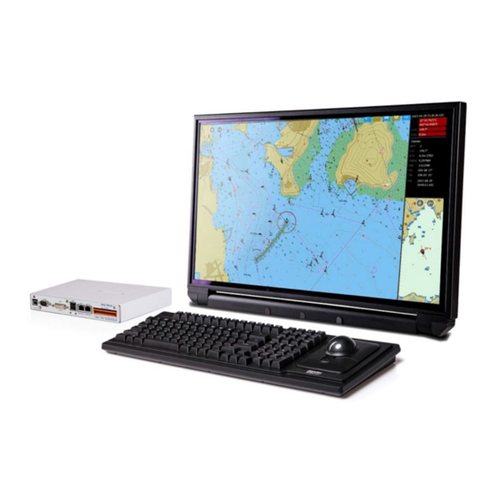
User manual for DM700 ECDIS hardware Copyright Danelec Marine A/S System overview for DM700 ECDIS 2.1 System overview A DM700 ECDIS consists of the following parts: Monitor Keyboard Power COM1 USB 4 DM700 ECDIS DPU 700-01 USB 2 HW-KEY M.2 SATA... -
Page 7: Dpu (Data Processing Unit)
The monitor is installed on a table top, or flush-mounted in the console. 2.1.5 Monitor HMI The monitor HMI is used to power the DM700 ECDIS ON and OFF. It also includes a buzzer which will sound if an alarm or warning condition occurs in the ECDIS. The monitor HMI is mounted on the monitor hinge or if the monitor is panel-mounted, installed adjacent to the monitor. -
Page 8: Ecdis Cluster
A complete ECDIS installation will in most cases consist of a number of systems (a cluster). The DM700 ECDIS can be connected directly together if the cluster contains only two systems. The DM700 ECDIS’s must be connected using an Ethernet switch if the cluster contains more than two systems. - Page 9 User manual for DM700 ECDIS hardware Copyright Danelec Marine A/S The DM700 ECDIS and DM800 ECDIS G2 can be combined in a cluster. It will not be possible to have redundant network connections if DM800 ECDIS G2 and DM700 ECDIS are used together...
- Page 10 User manual for DM700 ECDIS hardware Copyright Danelec Marine A/S DM800 DM800 DM700 ECDIS G2 ECDIS G2 ECDIS (Master) (Backup) (Planning) Port 1 Port2 Port 1 Port 2 LAN 1 Cluster containing 1 x DM700 ECDIS and 2 x DM800 ECDIS G2 MAN11804-10 Page 10/30...
-
Page 11: Monitor Hmi
The volume of the alarm signal may be adjusted in the ECDIS application. Go to the shortcut menu and adjust the volume using the buzzer volume controls. (see DBS11425 “User Manual for Danelec Marine ECDIS software” for further details). 3.2 ECDIS computer shutdown There are 2 ways to set the ECDIS to standby: ... -
Page 12: Hardware Standby
User manual for DM700 ECDIS hardware Copyright Danelec Marine A/S Click on “Standby” and click on [Standby]. 3.2.2 Hardware standby Note: The procedure described in this section should only be used if the ECDIS software freezes or stops responding to user input. -
Page 13: Monitor
User manual for DM700 ECDIS hardware Copyright Danelec Marine A/S Monitor 4.1 Control panel on monitor The brightness can be controlled from the ECDIS software (Main MenuSettingsSystemDisplay or Main MenuShortcuts). Note that the monitor is not calibrated unless is shown next to the brightness and contrast field. -
Page 14: Self-Test
User manual for DM700 ECDIS hardware Copyright Danelec Marine A/S Self-test The presence of the keyboard, trackball, and USB hardware key is monitored by the DPU. A caution will be generated if an error in one of these devices is detected. -
Page 15: Dm700 Ecdis Data Processing Unit (Dpu 700-01)
User manual for DM700 ECDIS hardware Copyright Danelec Marine A/S DM700 ECDIS data processing unit (DPU 700-01) DPU front panel DPU Back panel Power The DM700 main unit must be powered from the DC output on the monitor. The monitor must be connected to the ship’s main power source (110-230AC). -
Page 16: Status Led's
6.2.1 Status LED Off: The DM700 ECDIS is in standby or without power. Red: Reverse power protection is active. Green (normal operation): The DM700 ECDIS is powered on and is probably operating normally. Blue flash (normal operation): Disk activity. MAN11804-10... -
Page 17: System Management Menu
User manual for DM700 ECDIS hardware Copyright Danelec Marine A/S System Management menu The ECDIS includes a System Management menu for performing special non-standard tasks. Note: The System Management Menu should only be used by personnel with proper authorization, as incorrect use may result in loss of chart licenses. - Page 18 User manual for DM700 ECDIS hardware Copyright Danelec Marine A/S 5. Enter the MASTER password 6. The “Management menu” will now open. MAN11804-10 Page 18/30...
-
Page 19: Menu
This menu is used for updating the software of the system. Only software updated made and signed by Danelec Marine A/S can be installed. Software update requires the ECDIS to be restarted. See section 7.4 “Install software update” for further details. -
Page 20: Management Of Usb Hardware Keys
User manual for DM700 ECDIS hardware Copyright Danelec Marine A/S 7.2 Management of USB hardware Keys It may be necessary to reset or change roles of a USB hardware key if one of the existing hardware keys is replaced. In most cases this will be handled automatically by the system, but in cases where a USB hardware key has been used as primary key in another ECDIS cluster, the hardware key needs to be changed. -
Page 21: Usb Hardware Keys
User manual for DM700 ECDIS hardware Copyright Danelec Marine A/S 7.3 USB hardware keys The USB hardware key contains the USERPERMIT for the charts. If no hardware key is inserted, it is not possible to view imported charts. The hardware key can be used in two configuration types. -
Page 22: Software Version
User manual for DM700 ECDIS hardware Copyright Danelec Marine A/S Click on [Start Update]. Click [Yes]. The update process starts. After completion of the update the following is shown: When clicking [OK] the ECDIS will restart, and the the update is completed. -
Page 23: Verification Of System Software Version
User manual for DM700 ECDIS hardware Copyright Danelec Marine A/S Verification of System Software Version The system software on the ECDIS must be kept updated. Information about available versions, release status and compliance status may be found on the website: http://www.danelec-marine.com... -
Page 24: Hardware Errors
User manual for DM700 ECDIS hardware Copyright Danelec Marine A/S Hardware Errors The hardware is continually monitored, and the user is warned if any errors occur. Some errors can be removed by the user. Others will require a service technician. - Page 25 User manual for DM700 ECDIS hardware Copyright Danelec Marine A/S There is a communication problem 10232 Caution, Will only occur in a cluster with the primary USB hardware configuration. The primary USB key. The licensed charts will hardware key is not present in the...
- Page 26 User manual for DM700 ECDIS hardware Copyright Danelec Marine A/S Possibly a disconnected or defective network cable. Verify all network cables are connected correctly, and check that link is present for both Ethernet ports 1 and 2. 10401 Caution, Low disk space. Less than x MB The disk is almost full.
-
Page 27: Diagnose Errors/Malfunctions
2. Change monitor mode to DAY by pressing F6 on the keyboard up to three times. 3. Reset monitor settings at each monitor mode by pressing F8 in each monitor mode. 4. Check the DVI cable is connected to the DVI port of the DM700 ECDIS DPU, and the DVI port of the monitor. - Page 28 User manual for DM700 ECDIS hardware Copyright Danelec Marine A/S 3. Verify the DM700 ECDIS is turned on (Status LED must be GREEN). If not, briefly press the “POWER” button on the monitor HMI, or briefly press the “POWER” button on the DPU 700-01, next to the Status LED 4.
-
Page 29: Appendix A - Color Differentiation Test
To adjust the contrast and brightness do the following: 1. Make sure that the “Chart1” database is displayed (See DBS1425”User Manual for Danelec Marine ECDIS Software”). Open Main Menu NAV DATA Chart Library and enable “Display” of “Chart1”... - Page 30 User manual for DM700 ECDIS hardware Copyright Danelec Marine A/S c. the chart scale is larger than 1:16 500. 6. Open the shortcut menu Main Menu Shortcuts 7. First, set contrast to a maximum, and brightness to a minimum. Look at the black-adjust symbol.
Need help?
Do you have a question about the DM700 ECDIS and is the answer not in the manual?
Questions and answers