
Related Manuals for KUHN GA300GM


Summary of Contents for KUHN GA300GM
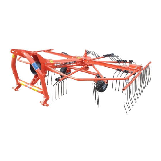
- Page 1 Operator's manual KN125DGB B Read carefully before starting the machine Gyrorake Original instructions KN125DGB B - English - 08-2019...
-
Page 3: Dear Owner
1. Dear Owner In buying a Kuhn machine you have chosen wisely. Into it have gone years of thought, research and improvement. You will find, as have thousands of owners all over the world, that you have the best that engineering skill and actual field testing can produce. -
Page 4: Table Of Contents
Gyrorake GA300GM 2. Contents Dear Owner ........................1 Contents ..........................2 Identification of the machine..................5 Front view ............................5 Rear view (working position)......................5 Identification of the machine ......................6 Optional equipment.......................... 8 Safety..........................9 Description of symbols used in this document................. 9 Safety instructions ......................... - Page 5 Gyrorake GA300GM Likely critical failures........................28 Incorrect use of the machine by the user ..................28 Limit state criteria........................... 28 Machine specifications....................29 Description and glossary ....................... 29 Technical specifications ......................... 30 5.2.1 Designated parameters ....................30 Sound levels ..........................31 Putting into service......................
- Page 6 Gyrorake GA300GM Optional equipment......................53 Front support wheel ........................53 9.1.1 Settings..........................53 9.1.2 Instructions for transport....................54 9.1.3 Instructions for work ......................55 Bogie axles ............................ 56 9.2.1 Machine use ........................56 9.2.2 Lubrication ........................57 Lateral signalling equipment ......................58 Europe signalling equipment ......................
-
Page 7: Identification Of The Machine
Gyrorake GA300GM 3. Identification of the machine Front view Rear view (working position) 3. - Identification of the machine KN125DGB B... -
Page 8: Identification Of The Machine
Do not remove the manufacturer, homologation and marking plates attached to the machine. 3.3.1 Location of the plates Note the serial number of your machine: • Serial Number: This information is to be given to the Kuhn authorized dealer for any spare parts order or warranty claim. 3.3.2 Description ... - Page 9 Gyrorake GA300GM Certification plate (CE) For machines aimed at countries which are members of the European Union (EC marking). 4: KUHN logo 26: Model Year 7: Model 24: Year of Construction 9: Machine serial number 7: Model 19: Plate reference 9: Serial Nr.
-
Page 10: Optional Equipment
Gyrorake GA300GM Optional equipment Tick box corresponding to the equipment fitted on your machine: Front support wheel. Bogie axles. Europe signalling equipment. USA signalling equipment. 3. - Identification of the machine KN125DGB B... -
Page 11: Safety
Gyrorake GA300GM 4. Safety Description of symbols used in this document This symbol indicates a potentially hazardous situation that if not avoided, could result in serious bodily injury. This symbol is used to identify special instructions or procedures which, if not followed strictly, could result in machinery damage. -
Page 12: Safety Instructions
It is too late to learn once work has been started! Never let anyone operate the machine who is not trained to do so. Should you have any difficulties in understanding any parts of this manual, please contact your KUHN dealer. 4. - Safety KN125DGB B... -
Page 13: Safety Decals
Gyrorake GA300GM 4.2.3 Safety decals Safety warning decals are placed in pictorial form on various parts of the machine. They are there to warn you of potential dangers and to tell you how to avoid accidents. Always keep the safety decals clean and readable, and replace them when they are worn, damaged, missing or illegible. -
Page 14: Precautions To Take Before Using The Machine
Gyrorake GA300GM 4.2.5 Precautions to take before using the machine Do not wear loose clothing which could become caught up in moving parts. Wear the appropriate protective clothing for the work in hand (gloves, shoes, goggles, helmet, ear defenders, etc.). -
Page 15: Precautions When Driving
Gyrorake GA300GM 4.2.6 Precautions when driving Tractor handling, stability, performance and braking efficiency are all affected by weight distribution, trailed or mounted implements, additional ballast and driving conditions. It is therefore of great importance that the operator exercises caution in every given situation. -
Page 16: Precautions When Driving On Public Roads
Gyrorake GA300GM 4.2.7 Precautions when driving on public roads Dimensions Depending on the dimensions of the machine, contact the relevant authorities to ensure that it can be legally transported on public roads. If the machine is over the maximum legal size, follow the local regulations for special transportation of oversize equipment. - Page 17 Gyrorake GA300GM Gross weight and weight per axle The drawings are not legally binding, their only aim is to illustrate the method to use. Prior to driving on public roads, check that all criteria are met to be in conformity with the...
- Page 18 Gyrorake GA300GM How to proceed: Stage 1: To measure: Tractor tare (T). T = _____kg T = ________ kg Stage 2: - Couple the machine to the tractor. To measure: - Load on front axle (t1): • Tractor + machine (transport position).
- Page 19 Gyrorake GA300GM Stage 3: To measure: - Total weight (t): • Tractor + machine (transport position). • Ballast weights. kg kg Checking: - To go to the next stage: • Check in the tractor's operator's manual that the value measured is below the tractor's Gross Combined Weight Rating.
-
Page 20: Maximum Speed
Gyrorake GA300GM 4.2.8 Maximum speed Always keep to the legal speed limit for driving a tractor-machine assembly on public roads. 4.2.9 Precautions when coupling Before attaching the machine, make sure that it cannot accidentally start moving (chock the wheels) and that the parking stand is in the right position. -
Page 21: Pto Shaft
Gyrorake GA300GM 4.2.10 PTO shaft Use only PTO shafts supplied with the machine or recommended by the machine manufacturer. The protective shield of the tractor PTO stub, the PTO shaft guards and the protective shield of the machine input shaft must always be in place and in good condition. - Page 22 Gyrorake GA300GM Before engaging the PTO drive, make sure that there are no people or animals near the machine. Never engage the PTO drive when the tractor engine is stopped. Do not install any adapter device that results in a portion of the tractor PTO stub, the rotating PTO shaft, or the adapter to be unguarded.
-
Page 23: Precautions During Manoeuvres
Gyrorake GA300GM 4.2.11 Precautions during manoeuvres When moving the machine from the transport position to the working position and vice versa, make sure that nobody is within the machine pivoting area. 4.2.12 Remote controlled components Danger of crushing and shearing can exist when components are operated by hydraulic or pneumatic controls. -
Page 24: Precautions For Maintenance And Repair Work
Gyrorake GA300GM 4.2.15 Precautions for maintenance and repair work Before leaving the tractor or before adjusting, maintaining or repairing the machine, disengage the PTO drive, turn off the engine, remove ignition key and wait until all moving parts have come to a complete stop and apply park brake. -
Page 25: Projection Of Stones And Foreign Objects
Gyrorake GA300GM 4.2.16 Projection of stones and foreign objects For driver safety, always use a tractor equipped with a cab. Keep the ground to mow free of foreign bodies. Avoid mowing on stony or rocky grounds. If this is not possible, take extra safety precautions,... -
Page 26: Precautions For Machine Use
Gyrorake GA300GM 4.2.17 Precautions for machine use Before using the machine, check tools (tines) and their attachment hardware in accordance with the instructions of the present manual. Check the guards regularly. Immediately replace any damaged or missing elements. Before engaging the pto drive, lower the rotors onto the ground. Make sure all the guards are in place. Keep all persons and animals away from the danger zone. -
Page 27: Location And Description Of Safety Decals On The Machine
Gyrorake GA300GM Location and description of safety decals on the machine 4.3.1 Location of safety decals 4. - Safety KN125DGB B... -
Page 28: Description Of Safety Decals
Gyrorake GA300GM 4.3.2 Description of safety decals Operating instructions (1) The operators' manual contains all the information necessary for using the machine safely. It is imperative to read and comply with all instructions. Working on the machine (2) - Page 29 Gyrorake GA300GM Rotary tools (4) To prevent entanglement keep a safe distance from the machine. 4. - Safety KN125DGB B...
-
Page 30: Likely Critical Failures
Gyrorake GA300GM Likely critical failures • 133993: Specific requirements for countries member of the Eurasian Economic Community (EAC marking). • 133994: Specific requirements for countries member of the Eurasian Economic Community (EAC marking). • 133995: Specific requirements for countries member of the Eurasian Economic Community (EAC marking). -
Page 31: Machine Specifications
Wheel Designated use of the machine The GA300GM Gyrorake must only be used for the work for which it has been designed: raking on the ground and forming windrows of pre-mowed fodder and straw. 5. - Machine specifications KN125DGB B... -
Page 32: Technical Specifications
Gyrorake GA300GM Technical specifications GA300GM Coupling device 3 point linkage category 1 and 2 Number of rotors Rotor diameter 2.64 m (8’8’’) Number of arms per rotor Number of tines per arm Working width (DIN 11220) 3.20 m (10’6’’) (with single windrow) Swath width 0.80 m (2’7’’) (approximately) -
Page 33: Sound Levels
Gyrorake GA300GM Sound levels Sound levels have been measured in accordance with the measuring methods as defined in: • NF EN ISO 4254-1 «Agricultural machinery - Safety - Part 1: General requirements». Weighted equivalent continuous acoustic pressure level at the driver's seat (closed cabin) L (A) eq: •... -
Page 34: Putting Into Service
Gyrorake GA300GM 6. Putting into service Coupling and uncoupling 6.1.1 Description of coupling elements • A PTO shaft (1). • A parking stand (2). • A 7-pin electric plug for the electrical signalling equipment (optional equipment). 6.1.2 Preparing the tractor The machine adapts to tractors fitted with a 3-point hitch coupler category 1 or 2. - Page 35 Gyrorake GA300GM Hitch pin parallelism - Adjust tractor lift rods so that hitch pins are parallel to the ground. Lateral adjustment of the lower links - Distribute the play on each side of the lift linkage. - Check that the stabilisers function properly (Adjustment, Locking / Unlocking).
-
Page 36: Coupling The Machine
Gyrorake GA300GM 6.1.3 Coupling the machine - Lower the tractor three-point linkage. - Position ball joints of tractor lower links in line with machine lower yokes. Categories of linkage For attachment category 1: - Place lower links in position (a). - Page 37 Gyrorake GA300GM - Attach the top link to the machine top hitch pin. - Secure with R-clip. - Adjust the top link length so that the machine is horizontal with regards to the ground. - Lower transport lock (1). - Lift the machine using the tractor lift linkage until the parking stand no longer rests on the ground: •...
-
Page 38: Electrical Connections
Gyrorake GA300GM 6.1.4 Electrical connections When optional equipment is used, follow specific procedures mentioned in the related section: • Optional equipment / Europe signalling equipment. • Optional equipment / USA signalling equipment. 6. - Putting into service KN125DGB B... -
Page 39: Pto Shaft
Gyrorake GA300GM 6.1.5 Pto shaft Before using the machine for the first time: - Grease the transmission. Check overlap of the u-joint drive shaft and adjust length if necessary to avoid any premature wear. The direction of rotation is shown on a decal. - Page 40 Gyrorake GA300GM Check that there is a minimum overlap of 250 mm (10’’) when the machine is in working position and the tractor in line with the machine. Never operate the PTO shaft at an angle X exceeding 30°. To avoid serious accidents, the PTO drive shaft guards must be properly in place and fixed with the chains provided.
- Page 41 Gyrorake GA300GM - Attach pto shaft guard chain in hole on machine side Lower PTO shaft support (1). Immediately replace any worn or damaged guard. 6. - Putting into service KN125DGB B...
-
Page 42: Uncoupling The Machine
Gyrorake GA300GM 6.1.6 Uncoupling the machine Park the machine on an even fairly level ground. From the transport position: - Lift transport lock (1). - Remove R-clip (1). - Lower parking stand (2). - Insert R-clip (1) to lock parking stand (2). - Page 43 Gyrorake GA300GM - Lower tractor lift linkage to rest the machine on the parking stand. - Disconnect the PTO shaft from the tractor. - Secure PTO shaft into its' support (1). When the following equipment is fitted: • Lighting and signalling.
-
Page 44: Instructions For Transport
Gyrorake GA300GM 7. Instructions for transport Before placing the machine into transport position: - Wait until the rotating parts have come to a complete stop. - Check that nobody is within the machine pivoting area. - If there is someone, make sure the person moves away. - Page 45 Gyrorake GA300GM - Lower transport lock (1). - Lift the machine with the tractor's three point linkage. The lock engages and locks the front frame. Make sure that transport lock (1) is fully engaged. The machine is in transport position.
-
Page 46: Conformity With The Road Regulations
Gyrorake GA300GM Conformity with the road regulations Before driving the machine on public roads, ensure that the machine complies with current highway code regulations. - Always keep to the legal speed limit for driving a tractor-machine assembly on public roads. -
Page 47: Instructions For Work
Gyrorake GA300GM 8. Instructions for work Before placing the machine in working position: - Check that nobody is within the machine pivoting area. - If there is someone, make sure the person moves away. Putting the machine into work position... - Page 48 Gyrorake GA300GM - Remove pin (1). - Move windrow curtain beam (2) to the required position (3): 4 positions are possible (3). - Insert and lock pin (1). - Lower the tractor three-point linkage to rest the machine on the ground.
-
Page 49: Adjustments In Working Position
Gyrorake GA300GM Adjustments in working position Before manoeuvring the machine: - Check that nobody is within the machine pivoting area. - If there is someone, make sure the person moves away. 8.2.1 Wheel height adjustment Before leaving tractor before adjusting,... - Page 50 Gyrorake GA300GM - Engage pin (1) in one of the 7 holes (2) corresponding to the required setting. Basic adjustment: • Position pin (3) in the fifth hole (1) of vertical adjustment plate. Make sure pin (1) is fully engaged.
-
Page 51: Swath Screen Adjustment
Gyrorake GA300GM 8.2.2 Swath screen adjustment There windrow curtain adjustment possibilities. • Lateral adjustment. • Lengthways adjustment. • Vertical adjustment. Lateral adjustment - Remove pin (1). - Move windrow curtain beam (2) to the required position (3): 4 positions are possible. - Page 52 Gyrorake GA300GM In light crop, the machine can form double swaths. Fold windrow curtain to form double windrows. Lengthways adjustment The lengthways adjustment is combined with the sideways adjustment. The windrow curtain can be set forwards or backwards according to the crop density and the windrow width adjustment.
- Page 53 Gyrorake GA300GM Vertical adjustment The windrow curtain can be adjusted in 3 positions: • (1):High position. • (2):Central position. • (3):Low position. - Remove bolts (1) and nuts (2). - Adjust swath screen position (3). - Reinstall bolts (1) and nuts (2): •...
-
Page 54: Machine Use
Gyrorake GA300GM Machine use Before engaging the tractor PTO drive: - Keep all persons and animals away from the machine danger zone. - Place the machine in working position. Before the machine engages the crop: - Engage the tractor PTO drive and accelerate progressively up to the desired PTO speed. -
Page 55: Optional Equipment
Gyrorake GA300GM 9. Optional equipment Front support wheel • Top link chain (2). • Front support wheel (1). The front support wheel enables improving ground contour adaptation. 9.1.1 Settings Check that the hitch frame is free to move after having fitted the support wheel. -
Page 56: Instructions For Transport
Gyrorake GA300GM Height adjustment - Move column in mounting bracket . - Insert the pin (1) in one of the holes (2). - Secure using R-clip. The adjustment is correct when : • Tines slightly skim the ground. • Tine arms are level. -
Page 57: Instructions For Work
Gyrorake GA300GM 9.1.3 Instructions for work The top link must be floating. - Replace upper link with chain (1). The chain is used for lifting the machine on headlands. - On the tractor side, insert top link pin (1) in the large chain link (2). -
Page 58: Bogie Axles
Gyrorake GA300GM Bogie axles The bogie axles improve the machine's floatation when working on irregular grounds. 9.2.1 Machine use Height adjustment - Lift the machine using the tractor's lift linkage. - Remove tube clip (1). - Pull on bogie axle (2) to free pin (3) from its housing. -
Page 59: Lubrication
Gyrorake GA300GM - Proceed the same way with the second bogie axle. Left and right bogie axles can be adjusted at different heights. 9.2.2 Lubrication Every 50 hours Grease: • Pivot points (1). 9. - Optional equipment KN125DGB B... -
Page 60: Lateral Signalling Equipment
Gyrorake GA300GM Lateral signalling equipment The machine can be fitted with specific signalling lights to comply with the road regulations. The side device is made up of the following components: • 2 signalling panels (1). • 2 amber reflectors (2). -
Page 61: Europe Signalling Equipment
Gyrorake GA300GM Europe signalling equipment The road safety equipment is mounted in the factory or by your authorized Kuhn dealer according to current safety regulations. The rear device is made up of the following components: • 2 signalling panels (1). -
Page 62: Usa Signalling Equipment
Gyrorake GA300GM USA signalling equipment To conform with the current road regulations, the machine must be fitted with specific signalling panels when driving on public roads 9.5.1 Coupling and uncoupling Electrical connection - Connect 7-pin plug to the tractor. -
Page 63: Maintenance And Storage
Gyrorake GA300GM 10. Maintenance and storage Before carrying out any maintenance or repairs on the machine, switch off the tractor engine, remove ignition key, wait until all moving parts have come to a standstill and apply park brake. Check that hydraulic hose valves are shut- off. -
Page 64: Lubrication
Gyrorake GA300GM 10.2 Lubrication The pictorials show the points to be greased. - Clean grease nipples before greasing. Lubricate with multi-purpose grease grade NLGI 2. 10.2.1 PTO shaft Before using the machine for the first time: - Grease the transmission. -
Page 65: Rotor
Gyrorake GA300GM 10.2.2 Rotor The reduction gearbox is lubricated for life with 1.2 kg (2.6 lb) of multi-purpose semi-fluid grease grade NLGI 0. The guiding cam is lubricated for life with multi- purpose grease NLGI 2. 10. - Maintenance and storage... -
Page 66: Lubricate The Following Parts
Gyrorake GA300GM 10.2.3 Lubricate the following parts Lubricate with multi-purpose grease grade NLGI 2. Grease • Rotor gears (1). • Rotor arm housings (1). In difficult or intensive work conditions, reduce greasing intervals of rotor arm housings. 10. - Maintenance and storage... - Page 67 Gyrorake GA300GM • Wheel supports (2 greasers) (1). Lubricate with SAE 80W90 gear oil. • Pivot points (1). 10. - Maintenance and storage KN125DGB B...
-
Page 68: Maintenance
Gyrorake GA300GM 10.3 Maintenance Before carrying out any maintenance or repairs on the machine, switch off the tractor engine, remove ignition key, wait until all moving parts have come to a standstill and apply park brake. Check that hydraulic hose valves are shut- off. -
Page 69: Storage
Gyrorake GA300GM 10.4 Storage 10.4.1 At the end of each season Avoid high pressure water jets on rotor and pivot points. - Clean the machine thoroughly. - Put the machine under cover in a dry place. - Clean and pack the connections between rotor arms and removable tine arms with never-seize grease. - Page 70 Gyrorake GA300GM 10.4.3 Storage • 139884: Specific requirements for countries member of the Eurasian Economic Community (EAC marking). • 139885: Specific requirements for countries member of the Eurasian Economic Community (EAC marking). • 139886: Specific requirements for countries member of the Eurasian Economic Community (EAC marking).
-
Page 71: Troubleshooting Guide
Gyrorake GA300GM 11. Troubleshooting guide Problem Cause Remedy Poor raking over the whole Tines too far from the Adjust wheel height. rotor width. ground. Adjust wheel height to Poor raking on one side of Rotor tilted towards the obtain same tine/soil the rotor. - Page 72 Gyrorake GA300GM Problem Cause Remedy Move swath screen forwards. Incorrect swath screen Crop ejection at the front position: Too much at the of the swath screen. rear. Reduce PTO speed. Incorrect swath screen Crop ejection underneath Move swath screen position: Too far away the swath screen.
-
Page 73: Appendix
Gyrorake GA300GM 12. Appendix 12.1 Calculating the load on an axle When coupling a tool to the front and/or rear 3-point lift linkage, the maximum authorized payload must not be exceeded. When coupling tools to the front and/or rear 3-point lift linkages, the maximum load on tractor's tires must not be exceeded. - Page 74 Gyrorake GA300GM Obtained Description Units Description Tractor unladen weight Unladen load on tractor front axle Empty load on tractor rear axle Axle loads (Tractor + machine) Load on front axle (Tractor + machine) Load on rear axle (Tractor + machine)
- Page 75 Gyrorake GA300GM 3) Calculation of the actual load on the front axle T1 real If the front tool (M1) is lighter than the minimum load required at the front (minimum), increase tool weight until the required minimum front load is reached.
- Page 76 Gyrorake GA300GM Table Actual value obtained by Value authorized Double value of the calculation according to operator's authorized capacity per manual tyre (2 tyres) Minimum front/rear ballasting Total weight < Load on front axle < < Load on rear axle <...
- Page 77 Gyrorake GA300GM Determining the machine weight (M2) and the position of its centre of gravity (d) If the data required to calculate the total weight, axle loads and minimum ballasting are not supplied, use the following method. - Tractor only: - T1: Load on front axle.
- Page 78 Gyrorake GA300GM - T: Axle loads. • Tractor only. T = _____kg Rear tool or front-rear combination If the total unit weight exceeds the tractor Gross Combined Weight Rating in accordance with the countrie's legislation, empty the hopper to travel on public roads.
- Page 79 Gyrorake GA300GM - t1: Load on front axle. • Tractor + machine. • Hopper empty. t1 = _____kg - t: Axle loads. • Tractor + machine. • Hopper empty. t = _____kg Calculating the rear tool weight (M2): M2 = t - T...
-
Page 80: Limited Warranty
KUHN equipment from an authorized KUHN dealer, that such equipment is, at the time of delivery to such purchaser, free from defects in material and workmanship, and that such equipment is covered under this Limited Warranty providing the machine is used and serviced in accordance with the recommendations in the Operator's manual. - Page 81 - The warranty claim is completed on line via extranet - www.kuhn.com or submitted on a KUHN warranty claim form and returned to the Company within one month after the date of failure or the date of problem becoming apparent.
- Page 82 $Specimen of the "Declaration of conformity" EC Declaration of conformity (European directive 2006/42/CE) The manufacturer: Manufacturer name and address declares that the product described hereafter: Brand Brand Machine Machine Type / Model : Type / Model Serial no. Serial no. - conforms to the requirements of the European directive 2006/42/CE.
- Page 84 KUHN S.A. - B.P. 50060 - F - 67706 SAVERNE CEDEX (FRANCE) KUHN-AUDUREAU SAS - B.P. 19 - F - 85260 LA COPECHAGNIERE (FRANCE) KUHN-BLANCHARD SAS - 24, route de Nantes - F - 44680 CHEMERE (FRANCE) KUHN-HUARD SAS - B.P. 49 - F - 44142 CHATEAUBRIANT CEDEX (FRANCE) KUHN-GELDROP B.V.
Need help?
Do you have a question about the GA300GM and is the answer not in the manual?
Questions and answers