
Related Manuals for KUHN GMD 400


Summary of Contents for KUHN GMD 400
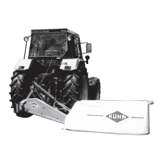
- Page 1 ASSEMBLY / OPERATOR'S MANUAL GMD 400 - 500 GMD 400 HD - 500 HD MULTIDISC MOWER N° 95001 C.GB - 03.2003...
- Page 2 DEAR OWNER, In buying a KUHN machine you have chosen wisely. Into it have gone years of thought, research and improvements. You will find, as have thousands of owners all over the world, that you have the best that engineering skill and actual field testing can produce. You have purchased a dependable machine, but only by proper care and operation can you expect to receive the performance and long service built into it.
-
Page 3: Table Of Contents
CONTENTS Safety Safety decals Assembly instructions Technical specifications General information Fitting to the tractor P.T.O. shaft Working position and adjustments Transport and parking the machine Operating the mower Lubrication Adjustments and maintenance Optional equipment Trouble shooting guide Storing the mower Limited warranty - 1 -... -
Page 4: Safety
DESIGNATED USE OF THE MACHINE The GMD 400 - 500 - 400 HD - 500 HD Disc Mowers must only be used for the work which they have been designed: mowing on the ground of hay fields, grass silage fields and improved pastures for the purpose of harvesting fodder for feeding livestock. - Page 5 GENERAL SAFETY RECOMMENDATIONS Before operating the machine, always ensure that tractor and machine are in accordance with work safety and road traffic regulations. BASIC PRINCIPLES 1. In addition to the recommendations given in this manual, legislation on work safety and accident prevention must also be respected.
- Page 6 18. Drive speed must be adapted to ground conditions as well as roads and paths. Always avoid abrupt changes of direction. 19. Precision steering, tractor adherence, road holding and efficient braking are influenced by the type of implement, weight, ballast of front axle, ground or road conditions. It is therefore of utmost importance to be cautious in every given situation.
- Page 7 ATTACHMENT 1. When attaching or removing the machine from the tractor, position hydraulic lift control lever in such a way that it cannot be set off accidentally. 2. When attaching the machine to tractor 3-point linkage, ensure that diameter of link pins corresponds to diameter of ball joints.
- Page 8 11. Never surpass PTO angle recommended by the manufacturer. 12. WARNING ! Rotating elements can continue turning momentarily after PTO is disengaged. Keep clear until all rotating elements are at a standstill. 13. When removing the machine, locate PTO shaft on the supports provided. 14.
- Page 9 4. Each time before using the mower, inspect condition of cutting elements (knives, discs). Replace any missing, worn or damaged cutting elements immediately. Use only genuine KUHN spare parts. 5. To avoid creating dangerous out of balance forces, always replace missing, damaged or worn knives in pairs.
- Page 10 6. When replacing knives or discs, systematically inspect their securing elements as per the manufacturer’s recommendations. 7. Regularly inspect the disc mower’s protection cover. Worn or damaged protection covers must be replaced immediately. 8. Protection devices (such as guards, shields etc.) are intended to prevent stones, rocks or other foreign objects from being projected.
-
Page 11: Safety Decals
SAFETY DECALS THE FOLLOWING SAFETY PICTORIALS HAVE BEEN PLACED ON YOUR MACHINE IN THE AREAS INDICATED. THEY ARE INTENDED FOR YOUR PERSONAL SAFETY AND FOR THE SAFETY OF THE PEOPLE WORKING WITH YOU. THE TEXT SHOWN ON THEM GIVES THEIR PRECISE MEANING. KEEP THE PICTORIALS LEGIBLE. - Page 12 - 10 -...
-
Page 13: Assembly Instructions
Lift system hydraulic Weight: - GMD 400 - 500 380 kg (836 lbs) 427 kg (939 lbs) - GMD 400 HD - 500 HD 386 kg (849 lbs) 434 kg (955 lbs) Bevel gearbox oil capacity 0.25 litre Oil quality : SAE 80 W EP (GL4) 0.53 US Pint / 0.43 Imp Pint... - Page 14 ASSEMBLY To facilitate shipping of the GMD 400 - 500 - 400 HD - 500 HD disc mowers, certain parts or assemblies are partially disassembled to reduce bulk. To assemble these parts proceed as follows : 1. Mounting chassis to cutterbar Make sure that the bore of nylon bushings is clean and well greased.
- Page 15 - Install belts (G) (photo 2) on pulleys and tension - Attach outer belt shield (E) with 3 washers and 3 cap them by loosening the 2 nuts (N) and tightening nut nuts (I)(photo 4). Torque to 5 daNm / 40 ft.lbs. (S) (photo 3).
- Page 16 Fit inner shoe (I) by means of 4 cup square bolts (J) - Attach the inner swathboard (D) (photo 8 A) in place (M 10 x 25) and 4 self locking nuts (M 10) (photo 8). using 4 (M10 x 20) round head bolts (E), 4 plain washers and 4 self-locking nuts.
- Page 17 The angular position of the swath wheel compared to the cutterbar can be adapted to working conditions enabling a regular flow of the cut crop towards the rear. Position the swath wheel so that maximum angle (A') (fig. 9 A) is obtained. In difficult working conditions (long, dense, bent over crops) position it towards minimum angle (A) (fig.
- Page 18 - Install cover (D) as shown in photo 12. Buckle straps around the pipe frame at E. Buckle straps (F) around front and rear safety bar. All these straps are attached to the underneath of the safety cover. - Punch 3 holes in the safety cover at (G) and use 3 cup square bolts (R) (M 10 x 35) with self-locking nuts (0) (M 10) (fig.
-
Page 19: General Information
2 linkages. 3. The GMD 400 - 500 - 400 HD - 500 HD are equipped with adjustable lower link pins allowing the machines to be offset 50 mm (2") to the left and to the right when mounted to a category 2 linkage and 114 mm (4.5") -
Page 20: Fitting To The Tractor
ATTACHING THE MOWER TO THE TRACTOR ATTACHMENT OF LOWER LINKS AND POSITIONNING OF LINK PINS : Follow fig. 1 for category 1 tractors with narrow wheel track. Follow fig. 2 for category 1 tractors with wider wheel track. Follow fig. 3 for category 2 tractors with narrow wheel track. - Page 21 1. Attach the lower links to the hitch pins and secure with linch pins shown at A (photo 16). 2. Attach the top link (B) using pin (C). Two positions are available on the pin, depending on the diameter of the ball joint, to secure the link to the mower . 3.
-
Page 22: P.t.o. Shaft
P.T.O. SHAFT Connect the PTO shaft to the 540 min tractor drive (with the free wheel fitted on the machine side). Make sure PTO length is correct : 1. When the PTO is in its maximum extended position, a minimum tube overlap of 150 mm (6") must be maintained. 2. -
Page 23: Working Position And Adjustments
WORKING POSITION AND ADJUSTMENTS Before putting the machine in work or transport position, ensure all persons are well clear of the cutterbar pivoting area. 1. Pressurise the lift cylinder so that the cutterbar closes up against its stop. 2. Pull cord (C) (photo 19) in order to free latch. 3. - Page 24 Adjustment of chassis height from the ground : 1. Tractors equipped with 3-point linkage with position control function : Set position control so that lower hitch pins are 400 mm (16") from the ground. 2. Tractors equipped with 3-point linkage without position control function (photo 21) : - Lower machine until the left lower hitch pin (A) is 400 mm (16"), or slightly more, from the ground.
- Page 25 SAFETY BREAKAWAY In rough field conditions the ground speed should be reduced. A breakaway latch allows the cutterbar to swing back if an obstruction is hit (photo 22). IF THE LATCH RELEASES, STOP THE TRACTOR IMMEDIATELY AND DISENGAGE THE PTO. To reset the cutterbar, back the mower until the cutterbar is in its normal position.
-
Page 26: Transport And Parking The Machine
TRANSPORT AND PARKING THE MACHINE Before transporting the machine on the pu- blic highway, the operator should make sure that the machine conforms to the highway code. 1° To transport the machine on public highways or from one field to another, proceed as follows : - Disengage the PTO drive and wait for all movement to stop. -
Page 27: Operating The Mower
OPERATING THE MOWER Release lock by applying pressure with the hand palm (arrow 1) and fold front safety bar (V) downwards (arrow 2) (photo 25) till it is automatically locked in working position. Ensure that the safety curtain is completely in place around the cutterbar. -
Page 28: Lubrication
Thereafter, oil must be changed every 200 hours of work and at least once per year. NOTE : Before draining oil, operate the cutterbar for a few minutes so that oil warms up. GMD 400 - 400 HD GMD 500 - 500 HD Quantity of oil in the bevel 0.25 litre / 0.53 US pint 0.25 litre / 0.53 US pint... - Page 29 2. CUTTERBAR Note : Make sure the cutterbar is in the vertical position when checking, adding or changing oil. The oil level is at its maximum when oil flows out of the filler plug hole. Check oil level once a day. Add SAE 80 W EP (GL4) oil to the cutterbar at filler plug (D) (photo 27).
-
Page 30: Adjustments And Maintenance
Worn or damaged items must immediately be replaced with genuine KUHN parts as otherwise warranty will be withdrawn. A) KNIVES : should be inspected systematically each time before the machine is operated. - Page 31 - When the contact washer has lost its elasticity or when it becomes loose from the nut. - When wear on the nut reaches a = 5 mm. FOR THE CORRECT OPERATION OF YOUR MACHINE, ALWAYS USE GENUINE KUHN SPARE PARTS. - 29 -...
- Page 32 (fig. A) it is fitted Torque locknut to 12 daNm / 90 ft.lbs. GMD 400 GMD 400 HD GMD 500 GMD 500 HD Fig. A...
- Page 33 (maximum two) distance spacer(s) (code 568 071 00) between the discs and the disc bearing stations (fig. B) (only for GMD 400 - 500) . Fig. B Important : Always replace securing elements (lock-nuts and bolts) when they have been removed 5 times.
- Page 34 (C) located underneath the safety guard (photo 31A). Note : Only replace belts as a complete set - No. 831 016 72 (GMD 400 - 400 HD) - No. 831 016 73 (GMD 500 - 500 HD). - 32 -...
-
Page 35: Optional Equipment
OPTIONAL EQUIPMENT 1. Hydraulic adaptators (photo 32) For fitting to different types of hydraulic connectors, three adaptators are available : M16 x 1,5 / 1/2 GAZ - CON 22 (823 012 05) M16 x 1,5 / 1/2 NPT - 24 (823 012 06) M16 x 1,5 / 3/4 UNF - JIC (823 019 02) - Page 36 4. Wear plate (568 017 00) To prolong the life of worn disc guards when working in very difficult and abrasive conditions, wear plates are available through our spare parts department for welding to the underside of each individual disc guard(fig. 35). 5.
-
Page 37: Trouble Shooting Guide
SERVICE ADJUSTMENT CHART PROBLEM CAUSE REMEDY Uneven stubble Too much tilt on cutterbar Reduce tilt (see page 22) Low PTO frequency Increase engine frequency to run PTO at 540 min Knives not installed Make sure that the arrow on the knife correctly upper face is pointing in the direction of rotation of the disc - see page 30) -
Page 38: Storing The Mower
STORING THE MOWER . Store the mower in a dry place. . Thoroughly clean the mower. . Drain oil from gearbox and cutterbar and refill with clean oil to correct level. . Inspect and replace worn knives and their fixation hardware. . - Page 39 SOUND LEVELS Sound levels given out by : GMD 400 - GMD 500 - GMD 400 HD - GMD 500 HD Multidisc Mowers Sound levels have been measured in accordance with the measuring methods as defined in: EN 1553 << Agricultural machinery - Agricultural self-propelled, mounted, semi-mounted and trailed machines - Common safety requirements >>...
-
Page 40: Limited Warranty
1. Normal maintenance such as greasing, maintenance of oil levels, minor adjustments, etc. 2. Transportation of any kind of any KUHN product to and from the place the warranty work is performed. 3. Dealer travel time to and from the machine or to deliver and return the machine from the workshop for repair. - Page 41 Company and have no right or authority to assume any obligation on their behalf, express implied, or to bind them in any way. KUHN S.A. reserves the right to incorporate any change in design in its products without obligation to make such changes on units previously manufactured.
- Page 42 - N O T E S -...
- Page 43 This machine complies with the safety requirements of the European machinery directive. The Operator should respect all Health and Safety regulations as well as the Highway Code. For your own safety, use only genuine KUHN spare parts. The manufacturer disclaims all responsibilities due to incorrect use or non-compliance with the...
- Page 44 KUHN parts KUHN S.A. 4 Impasse des Fabriques F - 67706 SAVERNE CEDEX (FRANCE) Tél. : + 33 (0) 3 88 01 81 00 - Fax : + 33 (0) 3 88 01 81 03 www.kuhnsa.com - E-mail : info@kuhnsa.com...
Need help?
Do you have a question about the GMD 400 and is the answer not in the manual?
Questions and answers