
Related Manuals for KUHN FC813R


Summary of Contents for KUHN FC813R
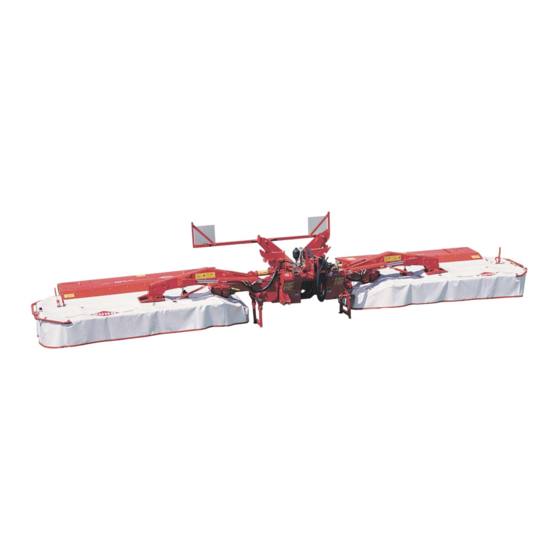
- Page 1 OPERATOR'S MANUAL KN013CGB K Read carefully before starting the machine Mower conditioner Original instructions KN013CGB K - English - 06-2016...
-
Page 3: Dear Owner
Designated use of the machine The FC813R mower conditioner must only be used for the work for which it has been designed: mowing on the ground of hay fields, grass silage fields and improved pastures for the purpose of harvesting fodder for feeding livestock. -
Page 4: Table Of Contents
Mower conditioner FC813R 2. Contents Dear Owner ........................1 Contents ..........................2 Identification of the machine..................5 Front view ............................5 Rear view ............................5 Model identification plate ......................... 6 Optional equipment.......................... 7 Safety..........................8 Description of symbols used in this document................. 8 Safety instructions ........................... 9 4.2.1... - Page 5 Mower conditioner FC813R Machine specifications....................31 Description and glossary ....................... 31 Technical specifications ......................... 34 Sound levels ..........................34 Putting into service...................... 35 Description of control elements ..................... 35 6.1.1 Positioning and parking ....................36 6.1.2 Description of the controls....................37 6.1.3...
- Page 6 Mower conditioner FC813R Optional equipment......................81 Raised skid shoes.......................... 81 Side deflector kit ..........................82 10. Maintenance and storage ....................83 10.1 Frequency chart ..........................83 10.2 Cleaning the machine ........................85 10.3 Lubrication ............................. 85 10.3.1 PTO shaft.......................... 86 10.3.2 Grease..........................88 10.3.3 Oil .............................
-
Page 7: Identification Of The Machine
Mower conditioner FC813R 3. Identification of the machine Front view Rear view 3. - Identification of the machine KN013CGB K... -
Page 8: Model Identification Plate
Mower conditioner FC813R Model identification plate Please write below the type and serial number of the machine. This information is to be given to the Kuhn authorized dealer for any spare parts order or warranty claim. KUHN S.A. 67700 SAVERNE - FRANCE FC813R ... -
Page 9: Optional Equipment
Mower conditioner FC813R Optional equipment Tick box corresponding to the equipment fitted on your machine: 1 3/4’’ - 6 spline yoke. 1 3/8’’ - 6 spline yoke. 1 3/4’’ - 20 spline yoke. 1 3/8’’ - 21 spline yoke. -
Page 10: Safety
Mower conditioner FC813R 4. Safety Description of symbols used in this document This symbol indicates a potentially hazardous situation that if not avoided, could result in serious bodily injury. This symbol is used to identify special instructions or procedures which, if not followed strictly, could result in machinery damage. -
Page 11: Safety Instructions
It is too late to learn once work has been started! Never let anyone operate the machine who is not trained to do so. Should you have any difficulties in understanding any parts of this manual, please contact your KUHN dealer. 4. - Safety KN013CGB K... -
Page 12: Precautions To Be Taken Before Carrying Out Any Operations On The Machine
Mower conditioner FC813R 4.2.3 Precautions to be taken before carrying out any operations on the machine Before leaving the tractor or before adjusting, maintaining or repairing the machine, disengage the PTO drive, turn off the engine, remove ignition key and wait until all moving parts have come to a complete stop and apply park brake. -
Page 13: Precautions When Driving
Mower conditioner FC813R 4.2.5 Precautions when driving Tractor handling, stability, performance and braking efficiency are all affected by weight distribution, trailed or mounted implements, additional ballast and driving conditions. It is therefore of great importance that the operator exercises caution in every given situation. -
Page 14: Precautions When Driving On Public Roads
Mower conditioner FC813R 4.2.6 Precautions when driving on public roads Dimensions Depending on the dimensions of the machine, contact the relevant authorities to ensure that it can be legally transported on public roads. If the machine is over the maximum legal size, follow the local regulations for special transportation of oversize equipment. - Page 15 Mower conditioner FC813R Gross weight and weight per axle The drawings are not legally binding, their only aim is to illustrate the method to use. Prior to driving on public roads, check that all criteria are met to be in conformity with the...
- Page 16 Mower conditioner FC813R How to proceed: Stage 1: To measure: - Tractor tare (T). T = _____kg Stage 2: - Couple the machine to the tractor. To measure: - Load on front axle (t1): • Tractor + machine (transport position).
- Page 17 Mower conditioner FC813R Stage 3: To measure: - Total weight (t): • Tractor + machine (transport position). • Ballast weights. Checking: - To go to the next stage: • Check in the tractor's operator's manual that the kg kg value measured is below the tractor's Gross Combined Weight Rating.
-
Page 18: Maximum Speed
Mower conditioner FC813R 4.2.7 Maximum speed Always keep to the legal speed limit for driving a tractor-machine assembly on public roads. 4.2.8 Precautions when coupling Before attaching the machine, make sure that it cannot accidentally start moving (chock the wheels) and that the parking stand is in the right position. -
Page 19: Hydraulic Circuit
Mower conditioner FC813R 4.2.9 Hydraulic circuit Caution! The hydraulic circuit is under high pressure. Maximum pressure at work: 200 bar. Before connecting hoses to the tractor hydraulics, ensure that tractor and machine circuits are not under pressure. Before disconnecting a hose, depressurize the hydraulic circuit. -
Page 20: Pto Shaft
Mower conditioner FC813R 4.2.10 PTO shaft Use only PTO shafts supplied with the machine or recommended by the machine manufacturer. The protective shield of the tractor PTO stub, the PTO shaft guards and the protective shield of the machine input shaft must always be in place and in good condition. - Page 21 Mower conditioner FC813R Before engaging the PTO drive, make sure that there are no people or animals near the machine. Never engage the PTO drive when the tractor engine is stopped. Do not install any adapter device that results in a portion of the tractor PTO stub, the rotating PTO shaft, or the adapter to be unguarded.
-
Page 22: Precautions During Manoeuvres
Mower conditioner FC813R 4.2.11 Precautions during manoeuvres When moving the machine from the transport position to the working position and vice versa, make sure that nobody is within the machine pivoting area. 4.2.12 Remote controlled components Danger of crushing and shearing can exist when components are operated by hydraulic or pneumatic controls. -
Page 23: Safety Decals
Mower conditioner FC813R 4.2.14 Safety decals Safety warning decals are placed in pictorial form on various parts of the machine. They are there to warn you of potential dangers and to tell you how to avoid accidents. Always keep the safety decals clean and readable, and replace them when they are worn, damaged, missing or illegible. -
Page 24: Precautions For Machine Use
Mower conditioner FC813R 4.2.16 Precautions for machine use After each use, check the cutting tools (discs, knives) their attachment hardware accordance with the instructions given in the present manual. Immediately replace any worn, damaged or missing cutting tool or element. To do this, use the tool outfit supplied with the machine. -
Page 25: Precautions For Maintenance And Repair Work
For your own safety and for correct machine operation, only use original manufacturer parts. It is strongly recommended to have your machine checked by your Kuhn dealer after each season, especially tools and their attaching hardware. 4. - Safety KN013CGB K... -
Page 26: Projection Of Stones And Foreign Objects
Mower conditioner FC813R 4.2.18 Projection of stones and foreign objects For driver safety, always use a tractor equipped with a cab. Keep the ground to mow free of foreign bodies. Avoid mowing on stony or rocky grounds. If this is not possible, take extra safety precautions,... -
Page 27: Location And Description Of Safety Decals On The Machine
Mower conditioner FC813R Location and description of safety decals on the machine 4.3.1 Location of safety decals 59900300 59900300 599011001 599011001 4. - Safety KN013CGB K... -
Page 28: Description Of Safety Decals
Mower conditioner FC813R 4.3.2 Description of safety decals Operating instructions (1) The operators' manual contains all the information necessary for using the machine safely. It is imperative to read and comply with all instructions. Working on the machine (2) - Page 29 Mower conditioner FC813R Projections (4) Stones and other debris projected by the moving parts can travel a long distance. The protection covers must always be in position and in good condition. Always stay at a safe distance from the machine.
- Page 30 Mower conditioner FC813R Cutting tools (7) The cutting tools and their attachment hardware meet safety and reliability criteria set by standards and by the manufacturer. For your own safety and for correct machine operation, only use original manufacturer parts.
-
Page 31: Road Safety Equipment And Recommendations
Mower conditioner FC813R Road safety equipment and recommendations The road safety equipment is mounted in the factory or by your authorized Kuhn dealer according to current safety regulations. To drive on public roads and to conform with the road regulations,... -
Page 32: Instructions Specific To France
Mower conditioner FC813R 4.4.1 Instructions specific to France To conform with the current road regulations, the machine must be fitted with specific signalling panels when driving on public roads. 4. - Safety KN013CGB K... -
Page 33: Machine Specifications
Mower conditioner FC813R 5. Machine specifications Description and glossary Side guard Left mowing unit Right mowing unit Lift cylinder Three-point hitch coupler Primary PTO shaft Secondary PTO shaft Mowing unit connecting frame Toolbox 10 : Signalling panel support 11 :... - Page 34 Mower conditioner FC813R Main frame Three-point hitch coupler Hitch pin Upper hitch attachment Pressure gauge Hoses holder Mowing unit connecting frame Hydraulic valve bank Transport lock 10 : Transport stop 11 : Hydro-pneumatic accumulator 12 : Ground pressure circuit valve...
- Page 35 Mower conditioner FC813R Rear hood Adjustment handle Side guard Conditioning roller Disk Cutterbar Large cone disc Side gearbox 5. - Machine specifications KN013CGB K...
-
Page 36: Technical Specifications
Mower conditioner FC813R Technical specifications FC 813R Attachment type 3 point linkage category 2 and 3 Number of discs 2 X 7 Working width (with a front mounted machine) 8.07 m (26’6’’) Width in working position 8.69 m (28’6’’) Width in transport position 2.98 m (9’9’’) -
Page 37: Putting Into Service
Mower conditioner FC813R 6. Putting into service Description of control elements The machine is supplied with an 18 mm box wrench (1) to carry out certain adjustment and maintenance tasks. The tractor must be equipped with: - 1 double acting valve for use in combination with the control box. -
Page 38: Positioning And Parking
Mower conditioner FC813R - 1 double acting valve for machine offsetting manoeuvres. - 1 single acting valve for setting the front unit in transport/work position and vice-versa. 6.1.1 Positioning and parking The control box must be easily accessible from the tractor cab. -
Page 39: Description Of The Controls
Mower conditioner FC813R 6.1.2 Description of the controls ON/OFF push button (a). The warning light is on when the control box is energized. The direction of operation of different functions may be inverted depending upon the way the hydraulic hoses have been connected to the tractor outlet. -
Page 40: Putting The Machine From Headland Turn Into Transport Position And Vice Versa
Mower conditioner FC813R 6.1.3 Putting the machine from headland turn into transport position and vice versa - Fold or unfold mowing units. Setting the machine into transport position is carried out with the machine in headland turn position. 6. - Putting into service... - Page 41 Mower conditioner FC813R Reduced or increased ground pressure - Increase or reduce mowing unit ground pressure. - Increase or reduce the front mounted mowing unit ground pressure. 6. - Putting into service KN013CGB K...
-
Page 42: Control Box Protection
Mower conditioner FC813R Putting the mowing units in headland turn position - Position switch in the following position: • Position (a) : Right mowing unit. • Position (b): Left and right mowing units. • Position (c): Left mowing unit. -
Page 43: Description Of The Connection
Mower conditioner FC813R 6.1.5 Description of the connection Never connect battery charger or perform welding tasks without having previously disconnected the control box. The control box is connected to: - A tractor 3-pin socket. - A machine wiring harness connected to the hydraulic valve bank. -
Page 44: Coupling And Uncoupling
Mower conditioner FC813R Coupling and uncoupling The machine adapts to tractors fitted with a 3-point hitch coupler category 2 or 3. 6.2.1 Description of coupling elements - A PTO shaft 1 3/4’’ - 6 splines (1). - A release cord (2). -
Page 45: Preparing The Tractor
Mower conditioner FC813R 6.2.2 Preparing the tractor Check that the tractor's authorized gross weight as well as its lift capacity and maximum weight per axle are not exceeded: See section: • Safety / Safety instructions / Precautions when driving on public roads. -
Page 46: Coupling The Machine
Mower conditioner FC813R Hitch pin parallelism - Adjust tractor lift rods so that hitch pins are parallel to the ground. 6.2.3 Coupling the machine - Lower the tractor three-point linkage. - Place the lower links as close as possible under the hitch pins. - Page 47 Mower conditioner FC813R • Category 3 (b). - Secure each hitch pin with lynch pin. - Attach top link (1). - Lock the upper hitch attachment using lynch pin (2). 6. - Putting into service KN013CGB K...
- Page 48 Mower conditioner FC813R - Raise machine using the tractor lift linkage until parking stands no longer rest on the ground. - Unlock and remove lynch pin (1). - Remove pin (2). - Raise parking stand (3). - Insert pin in hole corresponding to transport position (4).
-
Page 49: Hydraulic Connections
Mower conditioner FC813R 6.2.4 Hydraulic connections The machine hydraulic suspension circuit is pressurized at the factory. - Connect hydraulic hoses (1) and (2) to: • 1 double acting hydraulic outlet. - Connect offset cylinder hydraulic hoses (3) and (4) • 1 double acting hydraulic outlet. - Page 50 Mower conditioner FC813R Connection with a front mounted machine Use hose extension supplied with the machine. - Connect front mounted machine suspension adjustment hose (1) to rear machine coupler (2). - Connect front machine lift linkage hose (3) to a tractor single acting outlet.
-
Page 51: Electrical Connections
Mower conditioner FC813R 6.2.5 Electrical connections - Connect 7-pin plug to the tractor. - Connect control box to the 19-pin electric plug. 6. - Putting into service KN013CGB K... -
Page 52: Primary Pto Shaft
Mower conditioner FC813R 6.2.6 Primary PTO shaft Before using the machine for the first time: - Grease the transmission. Check overlap of the u-joint drive shaft and adjust length if necessary to avoid any premature wear. The direction of rotation is shown on a decal. - Page 53 Mower conditioner FC813R Never operate the PTO shaft at an angle X exceeding 30°. To avoid serious accidents, the PTO drive shaft guards must be properly engaged in the catches. - Check that the system is properly engaged. 6. - Putting into service...
-
Page 54: Intermediate Pto Shafts
Mower conditioner FC813R 6.2.7 Intermediate PTO shafts Before adjusting, maintaining or repairing the machine, turn off ignition key and wait until all moving parts have come to a complete stop. Before using the machine for the first time: - Grease the transmission. - Page 55 Mower conditioner FC813R - Remove the secondary PTO shaft from the central gearbox: • Place the machine in working position (a). • Press vertically on the 2 lugs using a screwdriver to release the PTO shaft guard (b). • Slide the guard along the PTO shaft (c).
- Page 56 Mower conditioner FC813R - Thread nuts away until they bottom against the threaded studs. The friction slip clutch is ready to function. Follow same procedure on the second mowing unit. 6. - Putting into service KN013CGB K...
-
Page 57: Adjusting The Machine
Mower conditioner FC813R 6.2.8 Adjusting the machine Lateral adjustment of the lower links Lateral adjustment of the lower links - Balance the play on either sides of the lift linkage and lock lower link stabilizers. - Check that the stabilisers function properly (Adjustment, Locking/Unlocking). -
Page 58: Uncoupling The Machine
Mower conditioner FC813R 6.2.9 Uncoupling the machine The machine must be uncoupled in working position. - Unlock and remove lynch pin (1). - Remove pin (2). - Lower parking stand (3). - Insert pin in one of the 3 parking stand upper holes corresponding to parking position (4). - Page 59 Mower conditioner FC813R Position a: Circuit open. Position b: Circuit closed. - Check that all suspension system valves are shut- off (3). - Disconnect hydraulic hoses and electric plug. - Place hydraulic hoses and electric signalling plug in their respective supports (4).
-
Page 60: Instructions For Transport
Mower conditioner FC813R 7. Instructions for transport Before placing the machine into transport position: - Wait until the rotating parts have come to a complete stop. - Check that nobody is within the machine pivoting area. - If there is someone, make sure the person moves away. - Page 61 Mower conditioner FC813R - Lock guards using bracket (2) and lynch pin (3). - Fold stop rod (4). Putting the machine in headland turn position - Place central switch in position (a). - Select the 2 mowing units using switch (1).
- Page 62 Mower conditioner FC813R Putting the machine into transport position - Place central switch in position (b). - Maintain switch (2) in position (c). - Activate tractor hydraulic outlet associated with the control box. Locks engage automatically. - Check that transport locks (4) are fully engaged.
- Page 63 Mower conditioner FC813R - Activate machine offset using the hydraulic offset cylinder to centre the frame. From the tractor cab, check that the offset mark (2) is in line with mark (3). - Shut-off the machine hydraulic circuit supply from the tractor cab.
- Page 64 Mower conditioner FC813R Never engage the tractor PTO drive when the machine is in transport position. Raise front mounted machine transport position. 7. - Instructions for transport KN013CGB K...
-
Page 65: Conformity With The Road Regulations
Mower conditioner FC813R Conformity with the road regulations Before driving the machine on public roads, ensure that the machine complies with current highway code regulations. - Check that the light boards are clean and that the lighting equipment functions before transporting the machine on public roads. -
Page 66: Instructions For Work
Mower conditioner FC813R 8. Instructions for work Putting the machine into work position Before placing the machine in working position: - Check that nobody is within the machine pivoting area. - If there is someone, make sure the person moves away. - Page 67 Mower conditioner FC813R Release locks - Place central switch in position (a). - Maintain switch (1) in position (b). - Activate tractor hydraulic valve connected to the control box to release locks. - Pull release cord until stop pins are released.
- Page 68 Mower conditioner FC813R Putting the machine into work position - Place central switch in position (b). - Select the 2 mowing units using switch (2). - Activate tractor hydraulic valve connected to the control box to lower the mowing units.
- Page 69 Mower conditioner FC813R - Lower stop rod (4). The machine is in working position. 8. - Instructions for work KN013CGB K...
-
Page 70: Putting The Machine In Headland Turn Position
Mower conditioner FC813R Putting the machine in headland turn position Before putting the machine into headland turn position: - Check that nobody is within the machine pivoting area. - If there is someone, make sure the person moves away. From the working position: - Place central switch in position (a). -
Page 71: Adjustments In Working Position
Mower conditioner FC813R Adjustments in working position 8.3.1 Cutting height The desired cutting height is obtained directly by adjusting the top link length. The height can be adjusted between 30 and 80 mm (1.1’’ - 3.1’’) depending on the tractors. -
Page 72: Ground Pressure
Mower conditioner FC813R 8.3.2 Ground pressure The ground pressure adjustment determins the safety breakback adjustment. Example: when the pressure in the gauges increases, the ground pressure of the mowing units decreases and the breakback force increases. The suspension of the mowing units is obtained by 4 hydro-pneumatic accumulators.By modifying the... - Page 73 Mower conditioner FC813R To check the ground pressure - Place the machine in working position. - Check that chassis height correct H = 600 mm (2’). - Check pressure indicated on gauges: • NORMAL operating pressure 130 bar (1885 psi).
- Page 74 Mower conditioner FC813R Adjust left mowing unit suspension - Shut-off valve of right mowing unit suspension system. Check that suspension circuit valve of left mowing unit is opened. - Place central switch in position (a). - Maintain switch (1) in position (b).
- Page 75 Mower conditioner FC813R • Check the pressure increase indication on the gauge. • Check the pressure decrease indication on the gauge. - When the required pressure is reached, close the valve. Proceed the same way for second mowing unit by inverting opening/closing of mowing unit suspension valves.
-
Page 76: Conditioning Intensity
Mower conditioner FC813R 8.3.3 Conditioning intensity Before adjusting, maintaining or repairing the machine, turn off ignition key and wait until all moving parts have come to a complete stop. Conditioning intensity is determined by the pressure exerted by the two rollers. -
Page 77: Swathing System
Mower conditioner FC813R 8.3.4 Swathing system The swathing system comprises: • 2 swath shields. Swath width adjustment - Loosen 2 handles (1). - Pivot swath shields inwards. - Tighten 2 handles (1). - The swath width can be adjusted of approximately 1.20 to 1.80 m (3’11’’... -
Page 78: Machine Use
Mower conditioner FC813R Machine use Before mowing and to reduce risks of projections, lower front guards. Keep all persons and animals away from the machine danger zone. Never lean or step on the protection cover. 8. - Instructions for work... - Page 79 Mower conditioner FC813R Before the machine engages the crop: - Engage the tractor PTO and slowly increase the speed up to 1000 min Only use the mowing unit lift cylinders to lift the machine from working position into headland turn position.
-
Page 80: Lateral Offset
Mower conditioner FC813R 8.4.1 Lateral offset During work, the machine frame can be offset laterally to avoid strips of uncut crop when turning or on slopes. When turning When turning at work, the overlap between the mowing units can be insufficient. - Page 81 Mower conditioner FC813R The frame must be offset towards the outer curb side. The offset increases the overlap up to D = 270 mm (10’6’’). - Position the central frame in line with the tractor when coming out of the curb.
-
Page 82: Drive Speed
Mower conditioner FC813R To adjust the overlap - Offset the rear machine: • Shift offset cylinder double acting valve. The frame must be offset uphill. The offset increases the overlap up to D = 270 mm (10’6’’). - Position main frame in line with the tractor on even field. -
Page 83: Optional Equipment
Mower conditioner FC813R 9. Optional equipment Raised skid shoes Kit no. 1076640 Equipment delivered depending on country. The raised skid shoes enable mowing higher, between 60 and 120 mm (2.4’’ - 4.8’’). - Replace the end disc skids by the 2 raised skid shoes. -
Page 84: Side Deflector Kit
Mower conditioner FC813R Side deflector kit Kit no. 1036330 The side deflectors are recommended for mowing dense or down crops with long stems. - Fit the 2 side deflectors on the outer side plates of the cutterbar stiffener. 9. - Optional equipment... -
Page 85: Maintenance And Storage
Mower conditioner FC813R 10. Maintenance and storage Before adjusting, maintaining or repairing the machine, turn off ignition key and wait until all moving parts have come to a complete stop. 10.1 Frequency chart Maintenance intervals are indicated for normal conditions of use. - Page 86 Mower conditioner FC813R Every 200 After the hours or at first 10 Every 30 Every 50 the end of hours of hours hours the season Grease: - Offset cylinder pivot pins. - Lift cylinder pivot points. - Offset linkage pivot points..
-
Page 87: Cleaning The Machine
Mower conditioner FC813R 10.2 Cleaning the machine - Regularly clean the build up between the conditioning hood and the support tube: • Lift and lock front guard. • Clean. • Lower and lock front guard. 10.3 Lubrication - Clean grease nipples before greasing. -
Page 88: Pto Shaft
Mower conditioner FC813R 10.3.1 PTO shaft Primary PTO shaft Before using the machine for the first time: - Grease the transmission. Check overlap of the u-joint drive shaft and adjust length if necessary to avoid any premature wear. - Every 250 hours: •... - Page 89 Mower conditioner FC813R Place the machine in working position. Stop the tractor engine and remove ignition key. The grease zerks of the secondary PTO shaft U- joints and guiding bushes are accessible by unlocking the 2 clips of the 2 guard cones (1).
-
Page 90: Grease
Mower conditioner FC813R 10.3.2 Grease - Offset cylinder pivot pins (1). - Lift cylinder pivot points (2). - Offset linkage pivot points (3). 10. - Maintenance and storage KN013CGB K... - Page 91 Mower conditioner FC813R - Transport stops and stop pins (5). Fold the machine in transport position to access the grease zerks. - Carrying frame pivot points (6). - Roller bearing housings: • Remove 3 bolts (1). • Remove chain guard (2).
-
Page 92: Oil
Mower conditioner FC813R • Remove 3 bolts (1). • Remove belt guard (2). • Grease roller bearing housing on belt drive side (3). • Reinstall belt guard (2). 10.3.3 Oil Roller drive chain To lubricate the chain: - Lubricate chain with SAE80W90GL5 oil through opening (1). -
Page 93: Oil Change
Mower conditioner FC813R 10.3.4 Oil change Cutterbars Before draining oil, operate the machine for a few minutes so that the oil warms up. The cutterbar is lubricated with 2 L (0.52 US gal) of extreme-pressure gear oil with viscosity grade SAE80W90 and API grade GL5. - Page 94 Mower conditioner FC813R Angle gearboxes Before draining oil, operate the machine for a few minutes so that the oil warms up. The angle gearbox is lubricated with 0.6 L (0.16 US gal) of extreme-pressure oil for mechanical transmissions with viscosity grade SAE80W90 and API grade GL5.
- Page 95 Mower conditioner FC813R Central gearbox Before draining oil, operate the machine for a few minutes so that the oil warms up. The angle gearbox is lubricated with 4 L (1.05 US gal) of extreme-pressure oil for mechanical transmissions with viscosity grade SAE80W90 and API grade GL5.
- Page 96 Mower conditioner FC813R - Check central gearbox oil level. • The oil level must reach the medium level of sight glass (4). Maximum level: (a). Minimum level : (b). 10. - Maintenance and storage KN013CGB K...
-
Page 97: Maintenance
Mower conditioner FC813R 10.4 Maintenance Before leaving tractor before adjusting, maintaining repairing machine, disengage the PTO drive, turn off the engine, remove ignition key and wait until all moving parts have come to a complete stop and apply park brake. -
Page 98: The Drive System
Mower conditioner FC813R To depressurize the circuit: - Place the machine in parking position. - Open valves (1). - Decrease pressure until gauges indicate 0 bar (0 psi). - Shut-off lock valves. Pressurize the hydraulic circuit before activating any other hydraulic function of the machine. -
Page 99: Stop Pins
Mower conditioner FC813R 10.4.3 Stop pins The stop pins enable locking the mowing units for transport. Adjustment: - Place the machine in working position. - Unscrew the 4 nuts (3). - Slide the stop pin (1) in the required position. -
Page 100: Checking The Oil Levels
Mower conditioner FC813R 10.4.4 Checking the oil levels Cutterbar - Periodically check the cutterbar oil level: • Place the cutterbar in horizontal position (with regards to X and Y axis). • Remove filler plug (1) and (2) as well as their seals. - Page 101 Mower conditioner FC813R Before checking that the discs rotate freely by hand: Turn off the engine, remove ignition key and wait until all moving parts have come to a complete stop. Follow same procedure on the second cutterbar. Central gearbox - Check central gearbox oil level: •...
-
Page 102: Inspection Of Knives And Securing Elements
Mower conditioner FC813R 10.4.5 Inspection of knives and securing elements Immediately replace worn or damaged parts with genuine KUHN parts. Knives - Inspect systematically all knives before the machine is operated to: • ensure the cutting quality. • ensure safety in use. - Page 103 Mower conditioner FC813R Securing elements - Check the securing elements: • After hitting an obstacle. • When replacing knives. • At the beginning of each season. - The fixing bolts should be changed in the following cases: • When there is visible distortion.
- Page 104 Mower conditioner FC813R Knife replacement Replace knife lock-nuts and bolts when they have been removed 5 times. Replace immediately all worn or distorted knives. Never straighten a bent knife. Always replace both knives per disc. - Clean the nut case.
-
Page 105: Disc Replacement
Mower conditioner FC813R 10.4.6 Disc replacement - Place a wooden wedge (2) between two discs to stop them from moving. - Remove 2 bolts (1) and their spring washers using the box spanner supplied with the machine. - Remove the disc conical cover. -
Page 106: Outer And Inner Cones
Mower conditioner FC813R 10.4.7 Outer and inner cones - Check torque of attachment bolts (1) of outer and inner cone covers (2) and (3): 6 daN m (44 lbf ft). - Replace any lost or damaged cover. (2) (Part no. 56803400) (3) (Part no. -
Page 107: Checking The Roller Parallelism And Gap
Mower conditioner FC813R 10.4.8 Checking the roller parallelism and gap Stop (1) located on each side of the conditioner are factory set to ensure the parallelism and minimum roller gap. Screw (1) and counter-nut (2) are coated with Loctite 243 when fitted. -
Page 108: Chain Replacement And Roller Synchronization
Mower conditioner FC813R Check parallelism over the whole roller width. - Readjust if necessary. Block screw and counter-nut. The use of Loctite 243 is recommended. Follow same procedure on the second mowing unit. 10.4.9 Chain replacement and roller synchronization To replace the chain: - Remove 3 bolts (1). - Page 109 Mower conditioner FC813R - Unscrew 2 bolts (1). - Pivot tensioning device slacken chain slightly (a). - Remove quick release link (3) and then chain (2). - Place wedge (1) between upright (2) and roller (3). - Rotate upper roller to balance the play on each side of the lower roller.
- Page 110 Mower conditioner FC813R If the chain is not tensioned : - Remove sprocket (2) and turn spline by spline (b) until proper tension is obtained. - Reinstall sprocket (2) with its washer and screw. • from C0001 to C0093: Torque: 8.5 daN m (63 lbf ft).
-
Page 111: Belts
Mower conditioner FC813R 10.4.10Belts Belt tension - Regularly check belt tension and in particular during the first hours of use. Loose belts slip excessively which reduces crop ejection quality and can cause conditioning rotor clogging. Checking the tension: The tensioning device ensures correct tension as long as washer (3) is in contact with tube (4). - Page 112 Mower conditioner FC813R Replacing the belts Never replace belts individually. When a belt is damaged, always replace the whole set (Part no. 83101681). - Remove 3 bolts (1). - Remove belt guard (2). - Loosen counter nut (3). - Loosen nut (4).
-
Page 113: Storage
Mower conditioner FC813R 10.5 Storage 10.5.1 At the end of each season - Clean the machine thoroughly. - Drain all gearboxes and cutterbar and refill with new oil: See section ’’Lubrication’’. - Touch up any areas of damaged paintwork. - Put the machine under cover in a dry place. -
Page 114: At The Start Of Each Season
Mower conditioner FC813R 10.5.2 At the start of each season - Re-read the operators' manual. - Pressurize the hydraulic circuit. - Check the condition of the friction slip clutch: See section ’’Secondary PTO shaft’’. - Inspect and replace worn knives and bolts: See section ’’Inspection of knives and securing... -
Page 115: Troubleshooting Guide
Mower conditioner FC813R 11. Troubleshooting guide Problem Cause Remedy Dull or broken knives. Replace knives. Make sure the arrow on Knives not installed the knife upper face is Uneven stubble. correctly. pointing in the disc's direction of rotation. - Page 116 Mower conditioner FC813R Incorrect main frame Adjust main frame height setting. with regards to the ground. Bad ground contour Excessive ground speed. Reduce groundspeed. adaptation. Insufficient ground Reduce accumulator pressure. pressure. Belts slip. Retension belts. Too low PTO speed Increase speed to Badly shaped windrows.
- Page 117 Mower conditioner FC813R Incorrect tractor lift linkage See machine attachment. setting. Insufficient cutterbar ground clearance in "headland turn" position. Too long levelling rod Shorten levelling rods on adjustment on tractor 3- tractor 3-point lift. point lift. The tractor valve does not Replace the faulty Mowing units do not lift.
- Page 118 Mower conditioner FC813R The control box is not Energize control box using energized. ON/OFF switch. Take hose in hand and Control box switches have The tractor valve does not feel if oil flows no effect on the cylinders. supply oil.
-
Page 119: Appendix
Mower conditioner FC813R 12. Appendix 12.1 Calculating the load on an axle When coupling a tool to the front and/or rear 3-point lift linkage, the maximum authorized payload must not be exceeded. When coupling tools to the front and/or rear 3-point lift linkages, the maximum load on tractor's tires must not be exceeded The load on the tractor front axle must always represent 20 % of the tractor unladen weight. - Page 120 Mower conditioner FC813R Obtained Description Units Description Tractor unladen weight Unladen load on tractor front axle Empty load on tractor rear axle Axle loads (Tractor + machine) Load on front axle (Tractor + machine) Load on rear axle (Tractor + machine)
- Page 121 Mower conditioner FC813R Front tool: 2) Calculation of the minimum rear ballast weight M2 minimum M1 x a - T2 x b + 0.45 x T x b minimum = b+c+d Write the minimal additional weight in the chart. 3) Calculation of the actual load on the front axle T1...
- Page 122 Mower conditioner FC813R Table: Actual value obtained Value authorized Double value of the by calculation according to authorized capacity operator's manual per tyre (2 tyres) Minimum front / rear ballasting Total weight < Load on front axle < <...
- Page 123 Mower conditioner FC813R Determining the machine weight (M2) and the position of its centre of gravity (d) If the data required to calculate the total weight, axle loads and minimum ballasting are not supplied, use the following method. - Tractor only: - T1: Load on front axle.
- Page 124 Mower conditioner FC813R - T2: Load on rear axle. • Tractor only. T2 = _____kg - T: Axle loads. • Tractor only. T = _____kg 12. - Appendix KN013CGB K...
- Page 125 Mower conditioner FC813R Rear tool or front-rear combination: If the total unit weight exceeds the tractor Gross Combined Weight Rating in accordance with the countrie's legislation, empty the hopper to travel on public roads. In any case, we recommend to travel on public roads with empty hoppers and tanks.
- Page 126 Mower conditioner FC813R - t: Axle loads. • Tractor + machine. • Hopper empty!. t = _____kg Calculating the rear tool weight (M2): M2 = t - T Calculating the distance (d): d = (( b x ( T1 - t1) ) / M2 ) - c 12.
- Page 127 Mower conditioner FC813R Front tool: If the total unit weight exceeds the tractor Gross Combined Weight Rating in accordance with the countrie's legislation, empty the hopper to travel on public roads. In any case, we recommend to travel on public roads with empty hoppers and tanks.
- Page 128 Mower conditioner FC813R - t: Axle loads. • Tractor + machine. t = _____kg Calculating the front tool weight M1 = t - T Calculating the distance (a): a = ( b x ( T2 - t2) ) / M1 12.
-
Page 129: Limited Warrantylimited Warranty
KUHN equipment from an authorized KUHN dealer, that such equipment is, at the time of delivery to such purchaser, free from defects in material and workmanship, and that such equipment is covered under this Limited Warranty providing the machine is used and serviced in accordance with the recommendations in the Operator's manual. - Page 130 - The warranty claim is completed on line via extranet - www.kuhn.com or submitted on a KUHN warranty claim form and returned to the Company within one month after the date of failure or the date of problem becoming apparent.
- Page 131 $Specimen of the "Declaration of conformity" EC Declaration of conformity (European directive 2006/42/CE) The manufacturer: Manufacturer name and address declares that the product described hereafter: Brand Brand Machine Machine Type / Model : Type / Model Serial no. Serial no. - conforms to the requirements of the European directive 2006/42/CE.
- Page 132 KUHN S.A. - B.P. 50060 - F - 67706 SAVERNE CEDEX (FRANCE) KUHN-AUDUREAU S.A. - B.P. 19 - F - 85260 LA COPECHAGNIERE (FRANCE) KUHN-BLANCHARD SAS - 24, route de Nantes - F - 44680 CHEMERE (FRANCE) KUHN-HUARD S.A. - B.P. 49 - F - 44142 CHATEAUBRIANT CEDEX (FRANCE) KUHN-GELDROP B.V.
Need help?
Do you have a question about the FC813R and is the answer not in the manual?
Questions and answers