Table of Contents
Advertisement
Quick Links
Important: Refer to technical data sheet TFP2300
for warnings pertaining to regulatory and health
information.
Scan the QR code or enter the URL in a web
browser to access the most up-to-date electronic
version of this document. Data rates may apply.
docs.jci.com/tycofire/indicator-post-supervisory-switch
The TYCO Model TIP Indicator Post Supervisory
Switch described herein must be installed and
maintained in compliance with this document, in
addition to the standards of any other authorities
having jurisdiction. Failure to do so may impair the
performance of the related devices.
The owner is responsible for maintaining their fire
protection system and devices in proper operating
condition. Contact the installing contractor or product
manufacturer with any questions.
NATIONAL FIRE PROTECTION ASSOCIATION and NFPA are registered trademarks of National
Fire Protection Association
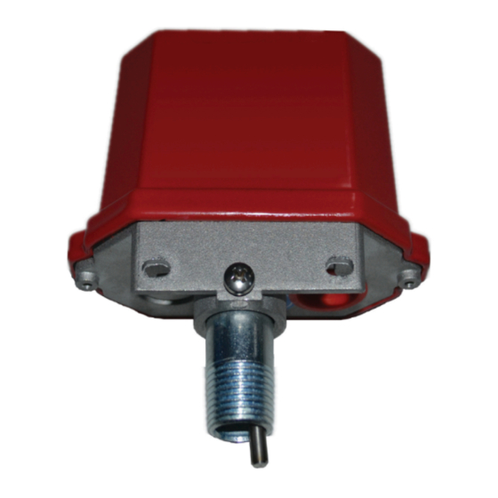
Model TIP Indicator Post Supervisory Switch
NOTICE
General description
The TYCO Model TIP Indicator Post Supervisory Switch is
designed to monitor the position of a wall and yard post
indicator type fire sprinkler control valve, and indicate
when the valve is not in the open position.
The switch is weather proof and tamper resistant. The
cover incorporates tamper resistant screws that require
a special tamper resistant key for removal. One tamper
resistant key is supplied with each device.
The unit mounts to a ½ in. NPT threaded hole in the post
indicator housing.
Models
The switch models are based on the number of sets of
single-pole, double-throw (SPDT) contacts as shown in
Table 1.
Table 1: Switch models
Model
TIP-1
TIP-2
APAC Only
TFP2112
MAY 2022
Description
1 set of SPDT contacts
2 sets of SPDT contacts
Advertisement
Table of Contents

Related Manuals for Tyco TIP


Summary of Contents for Tyco TIP
- Page 1 The TYCO Model TIP Indicator Post Supervisory Switch described herein must be installed and The TYCO Model TIP Indicator Post Supervisory Switch is maintained in compliance with this document, in designed to monitor the position of a wall and yard post...
- Page 2 Callout Dimension 4.55 in. (116 mm) 2.36 in. (60 mm) 5.04 in. (128 mm) Minimum: 0.50 in. (13 mm); Maximum: 2.00 in. (51 mm) 1.65 in. (42 mm) 1/2 in. NPT Model TIP Indicator Post Supervisory Switch APAC Only...
- Page 3 Installation Installing the switch Before you begin: The TYCO Model TIP Indicator Post Supervisory Switch must be installed according to the instructions in this • The switch must be installed according to the section. instructions in this section. Installation arrangements •...
- Page 4 Care and maintenance Limited Warranty The TYCO Model TIP Indicator Post Supervisory Switch For warranty terms and conditions, visit http://www.tyco- must be maintained and serviced in accordance with fire.com. this section, in addition to any specific requirements of Ordering Procedure the NFPA, and any impairment must be immediately corrected.
Need help?
Do you have a question about the TIP and is the answer not in the manual?
Questions and answers