
Related Manuals for Tyco VIGILANT MX 850EMT


Summary of Contents for Tyco VIGILANT MX 850EMT
- Page 1 850 Engineering Management Tool Australia/New Zealand User Manual LT0586 Doc. version 1.0 6 May 2015...
- Page 2 Copyright © 2015 Tyco Australia Pty Limited. All rights reserved. Tyco reserves the right to make changes to any aspect of this publication at any time without notice. VIGILANT is a trademark of Tyco New Zealand Limited or its affiliates; MX TECHNOLOGY is a trademark of Thorn Security Limited or its affiliates; TYCO is a trademark of Tyco International Services GmbH.
-
Page 3: Table Of Contents
Contents Guide through this manual ....................4 Keywords and symbols ......................4 Who is this Manual for ......................4 What Products are Covered by this Manual ................4 Introduction ........................... 5 Key Functions and Features....................6 Benefits of using 850EMT ..................... 6 Operating Instructions ...................... -
Page 4: Guide Through This Manual
Guide to this manual Keywords and symbols Who is this Manual for? This documentation uses special notations that you This user manual is aimed for the Installation, can use for better orientation. Symbols in the margins Commissioning and Service Engineers in Australia and indicate warnings, information or instructions. -
Page 5: Introduction
Its easy- and flexible tool used in the installation, commissioning, to-navigate screens capture user requirements in an diagnostics and servicing of Tyco MX detection systems. intuitive manner. The 850EMT allows all the MX addressable devices Fig. -
Page 6: Key Functions And Features
Key Functions and Features The 850EMT can be used as a desktop unit, clipped to a trouser belt or be carried using a shoulder strap. The key functions and features of the 850EMT are: • Two-way communication via infrared (IR) to 850 Series •... -
Page 7: Operating Instructions
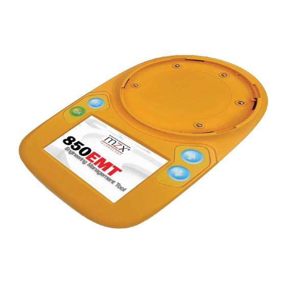
Operating Instructions Indicators and Controls The 850EMT is shown in Figure 3. The numbered items in the figure are explained in the following paragraphs. Fig. 3: 850 Engineering Management Tool 1 – Tool Base 2 – Escape Button 3 – OK Button 4 –... -
Page 8: Batteries
• Do not open the battery compartment Figure 4. cover while the unit is switched on, or charging • Ensure that only Tyco specified Nickel Metal Hydride rechargeable batteries are used and fully charged before use. Charging and Mains Use The 850EMT has its own built-in charging circuit, powered by an external adaptor. -
Page 9: Starting The 850Emt
Starting the 850EMT Logging On The screen shown in Figure 5 appears for about 3 seconds after the power is turned on (refer to Figure 1 #2). How to log on to the 850EMT In the PIN Entry screen, enter the 4-digit PIN 7240 by using the numeric keypad as shown in Figure 6 and press Enter. -
Page 10: Main Menu Screen
Main Menu Screen After the 4-digit PIN number has been successfully Buttons or Icons entered, the main menu screen appears as shown in Buttons/Icons are used for entering access codes, text Figure 7 . Detail on using the main menu is covered in strings or general information. -
Page 11: Connecting To An Mx Device
Connecting to an MX Device The 850EMT can be connected to MX detectors or • Tool Base: Communication between the 850EMT and ancillary devices using the tool base, the Ancillary lead, the device is possible by placing the detector in the or infrared communications. -
Page 12: Connecting To A Detector
Connecting to a Detector Detectors are connected to the 850EMT via the Toolbase as shown in Figure 8. Use the marking on the service tool (above ESC button) to align the detector. Place the detector in position 1 to engage and then twist clockwise to position 2 to lock. Fig. -
Page 13: Connecting To An Ancillary Device
Connecting to an Using IR Mode Ancillary Device Ancillary devices are connected to the ‘AUX’ socket using Using Infrared Mode the ancillary lead as shown in Figure 9. Infrared communications can be used with certain MX detectors and modules that contain the IR transceiver (currently 850 Series detectors and Quad I/O modules). -
Page 14: Menu Details
Menu Details Device Status The Main screen is displayed as shown in Figure 10. Use Device Status option to display the status/ configured settings of the device connected to the 850EMT. DOWNLOAD CONFIG An example Device Status screen is shown in Figure 11. COMMISSIONING MODE Device Status/Change Settings SERVICE MODE... -
Page 15: Change Address
Change Address CAUTION If the percentage of dirtiness is shown as 80% or above, the device may have degraded performance and should be The Change Address function allows the address of the replaced as soon as practicable. MX device to be changed. Press the Change Address button to show the Change Address Screen (see Figure 13). -
Page 16: Session Program
Session Program Use this option to program multiple devices with If you attempt to program an address that has already consecutive addresses. The 850EMT checks a table been used by an existing device, the message appears as ADDRESS ALREADY IN USE. In such a scenario: of addresses used, so the next unused address can be assigned to each device. -
Page 17: Reset Session Table
5.4.3 Reset Session Table Some functions may be greyed out and unavailable depending on the MX device (if any) that is connected. Use this option to reset the values displayed for the The operation of each test function is detailed in the Current Device Address and the Next Available following sections of this manual. -
Page 18: Test Outputs
5.5.2 Test Outputs This function allows the Remote LED and L2 (functional base) outputs of detectors to be tested. Note this function will fail on MX ancillaries. If the device is on the MX loop and connected via the IR mode, the Test Outputs screen appears as shown in Figure 20. -
Page 19: Short-Circuit Isolator
5.5.3 Short-Circuit Isolator 5.5.4 Blink-On-Poll Short-Circuit Isolator The blink-on-poll setting for a MX device can be changed This option works for only the 850 Series using the Blink-On-Poll screen shown in Figure 23. To Generation 6 detectors and range of Quad change the setting press YES or NO on the touch screen. -
Page 20: Self Test
5.5.5 Self Test 5.5.6 Change Tones This function is for changing the tones and beacon Entering the SELF TEST function performs a self test of settings for the MX Symphoni sounders and AVBase the supported sensors of a detector. devices. The function will be greyed out on the Test Functions menu unless a supported MX device is Initially PLEASE WAIT…... -
Page 21: 850Emt Settings
850EMT Settings Press the icon on the Main Screen to navigate to the 850EMT Settings screen as shown in Figure 27 . SET DATE ACCESS MANAGEMENT Fig. 29: Set Tones SET LANGUAGE 1 – Negative option is highlighted in red. 2 –... -
Page 22: Ordering Information
Ordering Information • LCD Brightness: Use this option to increase or decrease the clarity of the LCD display screen. Press this tab, the following screen appears as shown in Figure 31. Part Order Number 850EMT Service Tool Kit 850EMTK including carry case 5.7.1 Spares Accessories... -
Page 23: Appendix
Appendix Additional Information 6.1.1 Compatibility The 850EMT supports USB 2.0. The 850EMT is not compatible with all USB memory sticks. It is known to be compatible with the following memory sticks: • Freecom Traveller (supplied with this tool) • Kingston Data Traveller •... -
Page 24: Index
Index Numerics Enter Address 15, 16 850EMT SETTINGS Guide About 850EMT Access Management Activate the Isolator Hold Address Auto Auto-Program AUX Cable Indicators Indicators and Controls Information IR High Battery IR Link IR Low CAUTION Change Address Key Functions and Features Charging and Mains Use Keywords Charging Batteries... - Page 25 Pass WARNING Point 850EMT at Detector Point text Power Settings Zone text Reset Session Table Session Program Set Language Set Tones Short Circuit Isolator Spares Specifications Status Symbols Test Options Test Outputs Tool Base Using the Menus / 25 /...
- Page 26 LT0586 Version 1.0, 6 May 2015. Subject to change without notice. / 26 /...
Need help?
Do you have a question about the VIGILANT MX 850EMT and is the answer not in the manual?
Questions and answers