Table of Contents
Advertisement
Quick Links
Advertisement
Table of Contents

Related Manuals for Boyd E3010CB


Summary of Contents for Boyd E3010CB
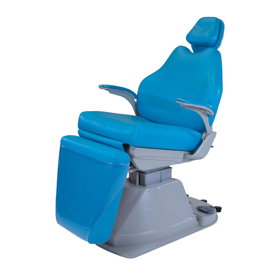
- Page 1 Product Information / Technical Service Manual E3010CB / M3010CB Treatment Chair 12900 44th Street North Clearwater, Florida 33762 800-255-2693 * 727-561-9292 FAX: 727-561-9393 SALES REV D FAX: 727-561-1682 SERVICE December 3, 2014 DOC. 9816...
-
Page 2: Table Of Contents
Table of Contents: Title Page Table of Contents Introduction Application of Product Warranty Information Safety Warning Symbols Safety Tips / Precautions About Your Chair Description of Product Line Standard Safety Features General Product Information Product Specifications Transport & Disposal Unpacking and Power Requirements Installation Instructions Operation Instructions 12-14... -
Page 3: Introduction
All BOYD manufactured products are warranted against defects in material or workmanship only. No other warranties are expressed or implied. This warranty shall extend for three (3) years for parts and one (1) year for labor. The BOYD warranty only covers products manufactured by BOYD. -
Page 4: Safety Warning Symbols
Safety Warning Symbols Caution: Risk of Electrical Shock Caution: General Danger Informational: Read Technical Informational: Read Operator’s Manual Before Servicing Manual Main Power Off Main Power On • Accessory Power On Accessory Power Off Light Type B Equipment Protective Earth Ground Earth Ground REV D December 3, 2014... -
Page 5: Safety Tips / Precautions
7. Heed warnings: Adhere to all warnings labeled on equipment and in owner’s manual. 8. Accessories: Use only accessories from Boyd Industries, Inc. catalog on this chair. Third party accessories will void the warranty and may be unsafe. 9. Cleaning: Use mild detergent in water on all painted surfaces and plastic parts. -
Page 6: About Your Chair
About Your Chair Description of Product Line Model: E3010CB / M3010CB Features: Power Back with synchronized leg Cantilever Style Lift Base Hand Controls Foot Control with Programming (optional) Standard Safety Features 1. Power Supply Chair is circuit breaker protected. 2. Hand Controls Hand Controls are located on both sides of the back section. -
Page 7: General Product Information
Upgrades are available Movement CB Base: Cantilevered Lift - 14.00” (355mm) Back / Synchronized Leg: Electric Actuator Net Weight E3010CB / M3010CB: 297 lbs (135 kg) Electrical 24V D/C low voltage motors Microprocessor controlled Chair operates at 24V D/C Power Supply... -
Page 8: Product Specifications
About Your Chair (continued) Product Specifications E3010CB / M3010CB 28.25 WITH ARMS 24.25 w / o ARMS 58.13 TOP VIEW Note: Headrest height is adjustable approximately 6”. 66.25 32.75 TO TOP OF SEAT FRAME 25.75 SIDE VIEW FULL UP POSITION 18.75 TO... - Page 9 Disposal of Boyd equipment: Boyd chairs are designed and built to last and provide efficient and safe service for many years. The expected service life of the E3010CB / M3010CB is 15 years. When the time finally comes to retire the chair, please dispose of the equipment according to statutory and regulatory requirements.
-
Page 10: Unpacking And Power Requirements
Unpacking and Power Requirements Unpacking Preassembly Check: Open shipping cartons carefully and check to see that all parts are received and have not been damaged during shipping. Unpacking Chair: Carefully remove two (2) fasteners securing chair to pallet using nut driver supplied with order. Slide chair from pallet to proper moving equipment and secure to move chair to final installation location. -
Page 11: Installation Instructions
Installation Instructions Fully Assembled Chair Model: E3010CB / M3010CB Location: Full size templates are available upon request for laying out location of chair and utilities (if required) prior to actual installation. Caution: Base must be anchored to floor. Failure to do so may result in serious bodily injury to operator and/or patient and could cause unwarranted product damage. -
Page 12: Operation Instructions
Operating Instructions E3010CB / M3010CB Series Chair Programming Instructions: Read these instructions completely before you begin programming. Using the chair up and down or back up and down controls, position the chair as desired. Wait at least three (3) seconds and push and hold the save button (S) for four (4) seconds, (system will issue a confirmation beep). - Page 13 Operating Instructions (continued) E3010CB / M3010CB Series Chair Standard: Foot Control E3010CB Optional: Foot Control M3010CB P/N 15-1195 115V. Note: Chair movement can be stopped by depressing any directional control (i.e. back up / back down, base up / base down, or any programmed position).
- Page 14 Operating Instructions (continued) E3010CB / M3010CB Series Chair Headrest Release (All Models) Headrest height adjustment: To lower or raise the headrest; support the headrest with one hand and push the release lever down with the other. Lower or raise the headrest to desired height.
-
Page 15: General Maintenance And Care
Use only cleaners and disinfectants approved for cleaning vinyl. Do not use strong or harsh cleaners as they may cause the vinyl color to fade. Apply the cleaner to a towel, not directly to the vinyl. Refer to vinyl manufacturer’s data on Boyd’s website for cleaning products. -
Page 16: Schematic Wiring Diagrams
Schematic Wiring Diagrams 115 VAC Electrical Component Diagram, E3010CB / M3010CB Foot Control and Cable are Optional REV D December 3, 2014 DOC. 9816... - Page 17 Schematic Wiring Diagrams (continued) 115 VAC Electrical Schematic, E3010CB / M3010CB All foot control switches are momentary N.O. REV D December 3, 2014 DOC. 9816...
- Page 18 Schematic Wiring Diagrams (continued) Electrical Parts Listing (Ref. Diagrams on pages 16 and 17) 10-4580 Linak CB6 Control, 115V 10-2250 Switch, Circuit Breaker, 10A, 115V 15-0910 Electric Distribution Box, 115V 10-4546 Linak DJB 15-1195 Foot Control, 2 Pedal (Optional) 15-1182 T-Cable, Linak 15-0115 Coiled Cable, Foot Control (Optional)
-
Page 19: Parts Breakdown
Parts Breakdown E3010CB / M3010CB Base View “A” Optional Foot Control and Cable REV D December 3, 2014 DOC. 9816... - Page 20 Parts Breakdown (continued) E3010CB / M3010CB Base View “B” Control Cable Base Motor Back Input Motor REV D December 3, 2014 DOC. 9816...
- Page 21 Parts Breakdown (continued) Parts Listing E3010CB / M3010CB Base (Ref. Diagrams on pages 19 and 20) 91-2280 Floor Plate 59-4819 Screw, Phil Pan #10-24 X 3/4 “F” 10-4610 Motor, Linak LA34 15-1117 Cable, AC Outlet 90-1653 Pin, LA34 Motor 10-1447...
- Page 22 Parts Breakdown (continued) E3010CB / M3010CB Frame REV D December 3, 2014 DOC. 9816...
- Page 23 Parts Breakdown (continued) Parts Listing E3010CB / M3010CB Frame (Ref. Diagram on page 22) REV D December 3, 2014 DOC. 9816...
- Page 24 Never attempt to move the chair by pushing on the armrests assemblies. Doing so will deform the armrest. Armrests are a standard feature on the E3010CB and available as an option on the M3010CB. REV D December 3, 2014 DOC.
-
Page 25: Light Post Assembly
Parts Breakdown (continued) Light Post Assembly E3010CB / M3010CB Chair is Shown with Right Side Light Post Assembly 90-1164 ADAPTER, INSERT, LIGHT 91-9194B LIGHT POST, 46", BLACK 91-9194 LIGHT POST, 46" 91-2502B LIGHT POST CUP, BLACK 91-2502 LIGHT POST CUP 59-5940 SSCUPSKT 0.3125-18x0.5-HX... - Page 26 Parts Breakdown (continued) E3010CB / M3010CB Upholstery Package Refer to the next pages for upholstery installation and removal 67-3005 ARMREST, M300X / M3000 67-4450 UPHOLSTERY: BACK 67-3012 LEG UPHOLSTERY ASSEMBLY, 3010 67-3011 UPHOLSTERY: SEAT ITEM NO. QTY. PART NO DESCRIPTION...
-
Page 27: Upholstery
Installation: E3010CB / M3010CB Upholstery E3010CB / M3010CB seat upholstery– The back upholstery must be in place before installing the seat upholstery (see previous page). Place the hangers located toward the top of the seat upholstery into the slots on the back frame and slide upholstery downward until it stops on hangers. -
Page 28: Troubleshooting Guide
Trouble Shooting Guide Symptoms: Appropriate Action: Chair will not operate Check the main ON/OFF switch (C1) to ensure that it is ON, it will be illuminated if it is on. Chair will not operate Check the A/C outlet that the chair is plugged into to insure that there is power going to the chair. Also check the building’s circuit breakers. -
Page 29: Electromagnetic Immunity Data
The Boyd model E3010CB / M3010CB Chair is intended for use in the electromagnetic environment specified below. The customer or the user of the Boyd model E3010CB / M3010CB should assure that they are used in such an environment. Compliance... - Page 30 RF communications equipment and the Boyd models E3010CB / M3010CB The Boyd model E3010CB / M3010CB are intended for use in an electromagnetic environment in which radiated RF disturbances are controlled. The customer or the user of the Boyd model E3010CB / M3010CB can help prevent...
- Page 31 The Boyd model E3010CB / M3010CB are intended for use in the electromagnetic environment specified below. The customer or the user of the Boyd model E3010CB / M3010CB should assure that they are used in such an environment. Electromagnetic environment –...
- Page 32 The Boyd model E3010CB / M3010CB are intended for use in the electromagnetic environment specified below. The customer or the user of the Boyd model E3010CB / M3010CB should assure that they are used in such an environment. Emissions test Compliance Electromagnetic environment –...
Need help?
Do you have a question about the E3010CB and is the answer not in the manual?
Questions and answers