Table of Contents
Advertisement
Quick Links
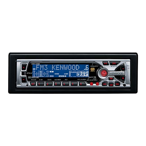
CASSETTE RECEIVER
KRC-579R/RY
QQ
3 7 63 1515 0
SERVICE MANUAL
KRC-579R/RY (E)
TE
L 13942296513
The following reference numbers with accessory parts are the same reference numbers
used on EXPLODED VIEW and PARTS LIST.
www
.
KRC-579R
CR2
K3I
47W x 4
LOUD
B NR
SCAN
B.S/RDM
201
277
x
ao
u163
y
i
2 9
8
PROG/PTY
REP
MTL/M.RDM
T I
VOL ADJ
Q Q
3
6 7
1 3
1 5
222
x2
DC1
259
co
.
9 4
2 8
© 2001-4 PRINTED IN KOREA
B51-7794-00 (K) 1947
PWR OFF
AUD
DISP
NAME.S
0 5
8
2 9
9 4
2 8
278
m
9 9
9 9
Advertisement
Table of Contents

Related Manuals for Kenwood KRC-579R


Summary of Contents for Kenwood KRC-579R
- Page 1 CASSETTE RECEIVER KRC-579R/RY 3 7 63 1515 0 SERVICE MANUAL © 2001-4 PRINTED IN KOREA B51-7794-00 (K) 1947 KRC-579R/RY (E) KRC-579R PROG/PTY PWR OFF 47W x 4 LOUD B NR SCAN B.S/RDM MTL/M.RDM DISP NAME.S VOL ADJ L 13942296513 The following reference numbers with accessory parts are the same reference numbers used on EXPLODED VIEW and PARTS LIST.
- Page 2 VOLTAGE DRIVER LIMITTER BACK UP MOT+B MAIN MOT ILL AVR V-ILL TYPE TYPE RESET RESET REMO REMO KRC-509S/689 (K/M) PANEL G/R SW G/R SW MATRIX DRIVER MATRIX U-COM KRC-579R/RY (E) u 1 6 3 KRC-609,679R/RY,781R/789 (K/E/M) KRC-V679R/RY (E) LCD DRIVER...
-
Page 3: Component Description
KRC-579R/RY 3 7 63 1515 0 COMPONENT DESCRIPTION SYNTHESIZER UNIT (X14-xxxx-xx) FUNCTION OPERATION Q1-4 PREOUT MUTE SW Preouts are muted when the base level goes "H". Q17,20 AUDIO 8V AVR Q20 is turned on when Q17's base level goes "H". -
Page 4: Microcomputer's Terminal Description
KRC-579R/RY 3 7 63 1515 0 MICROCOMPUTER'S TERMINAL DESCRIPTION (X14-) IC1 : SYSTEM µ-COM PORT PORT NAME FUNCTION OPERATING CONDITION AM+B AM power supply. "H" : During receiving AM. FM+B FM power supply. "H" : During receiving FM. "H" : During receiving. - Page 5 KRC-579R/RY 3 7 63 1515 0 MICROCOMPUTER'S TERMINAL DESCRIPTION (X14-) IC1 : SYSTEM µ-COM PORT PORT NAME FUNCTION OPERATING CONDITION ILLUMI-ON Illumination. "H" : Illumination on. "L" : Illumination off. 53,54 BVDD Power supply. BVSS GND. TYPE-2 I/O Destination SW.
-
Page 6: Test Mode
KRC-579R/RY 3 7 63 1515 0 TEST MODE TEST MODE • Balance is adjusted in 3 steps of Left Max/Center/Right 1. How to enter the test mode Max with the Track Up/Down keys. While holding the FM and Preset 6 keys, reset the unit. - Page 7 KRC-579R/RY 3 7 63 1515 0 TEST MODE 11. Other specifications (3) The security code is cleared and the unit enters the • Automatic panel closing when a tape/CD is inserted is ALL OFF mode. inhibited. (M&T model) (4) If you commit a mistake in the code entry, the unit •...
- Page 8 KRC-579R/RY 3 7 63 1515 0 ADJUSTMENT BALANCE/FADER/BASS/TREBLE : CENTER T.ADV/METAL/DOLBY NR/AUTO : OFF INPUT OUTPUT RECEIVER ALIGNMENT ITEM ALIGN FOR FIG. SETTINGS SETTINGS SETTINGS POINTS CASSETTE DECK SECTION Connect an DOLBY VR1 (L ch) AC voltmeter TCC-130 TAPE PLAY...
- Page 9 PC BOARD (Component side view) (X14-) 3 7 6 3 1 5 1 5 0 Ref. No. IC1 IC2 IC4 IC10 IC11 IC13 IC15 IC16 Q1 Q2 Q3 Q4 Q17 Q18 Q20 Q21 Q22 Q23 Q24 Q25 Q26 Q27 Q28 Q29 Q30 Addtess 5E 2H 2H 2H 2H SWITCH UNIT...
- Page 10 PC BOARD(Foil side view) (X14) 3 7 6 3 1 5 1 5 0 Ref.No. IC1 IC2 IC4 IC10 IC11 IC13 IC15 IC16 Q1 Q2 Q3 Q4 Q17 Q18 Q20 Q21 Q22 Q23 Q24 Q25 Q26 Q27 Q28 Q29 Q30 Address 2O 2P 2O 2O SWITCH UNIT...
- Page 11 5.6 1W OUT 2 C102 CD 2 0.1V TYPE SET (X14-xxxx-xx) DC CORD DC CORD MODEL D38, R113, R114, R341, R330,346 KRC-679R/RY (E) KRC-579R/RY (E) R104 R288 R319 R320 R321 R322 R323 R324 R347 R376 W102 615,616 NAME KRC-V679R/RY (E) KRC-789...
- Page 12 L CE R370 470 L CLK D GND D GND ILL GND KRC-509S/689 (K/M) (1/2) VDD 1 SW 1 KRC-579R/RY (E) (1/2) ILL+B S.GND SRT MECHA. KRC-609,679R/RY,781R/789 (K/E/M) w w w (Ref. No. 762) SW 2 KRC-V679R/RY (E) (1/2) u 1 6 3 Manufacture under license from Dolby Laboratories.
- Page 13 1 6 3 DAP202K 02CZ3.6-Z TC74HC02AF TDA7479D KRC-579R/RY (E) (2/2) CAUTION: For continued safety, replace safety critical components only with manufacturer's rec- ommended parts (refer to parts list). indicates safety critical components. For continued protec- KRC-579R/RY tion against risk of fire, replace only with same type and rating fuse(s). To reduce the risk of electric shock, leakage-current or resistance measurements shall be carried out (exposed parts are acceptably insulated from the supply circuit) before the appliance is returned to the customer.
-
Page 14: Exploded View (Mechanism)
KRC-579R/RY 3 7 63 1515 0 EXPLODED VIEW (MECHANISM) L 13942296513 u163 D40-1147-05 Parts with exploded numbers larger than 700 are not supplied. -
Page 15: Exploded View (Unit)
: N80-3008-46 M3x14 : N84-3014-46 M3x4 : N09-4368-05 M3x5 : N09-4318-05 (X14-) L 13942296513 (X16-) (X14-) (X14-) (X14-) (X16-) (X13-) (X13-) (X13-) (X13-) (X13-) (X13-) (X13-) (X13-) u163 KRC-579R/RY (E) Parts with exploded numbers larger than 700 are not supplied. -
Page 16: Parts List
✽ E59-0835-05 H25-1108-04 PROTECTION BAG (100X300X0.03) RECTANGULAR PLUG H25-1111-04 PROTECTION BAG (280X450X0.03) E2 ✽ H54-2055-03 ITEM CARTON CASE (KRC-579R) E2 R90-1016-05 MULTI-COMP 470 X4 E2 : KRC-579R indicates safety critical components. E : Europe K : North America M : Other Areas... -
Page 17: Synthesizer Unit (X14-Xxxx-Xx)
CHIP C 0.010UF C366,367 CC73GCH1H471J CHIP C 470PF C98 ,99 CK73GB1A224K CHIP C 0.22UF C380,381 CK73GB1H103K CHIP C 0.010UF E2 : KRC-579R indicates safety critical components. E : Europe K : North America M : Other Areas E5 : KRC-579RY... - Page 18 CHIP R 1/16W R342-344 RK73GB1J471J CHIP R 1/16W R100 RD14DB2H332J SMALL-RD 3.3K 1/2W R345 RK73GB1J104J CHIP R 100K 1/16W E2 : KRC-579R E : Europe K : North America M : Other Areas E5 : KRC-579RY indicates safety critical components.
- Page 19 DIGITAL TRANSISTOR MA8068-M ZENER DIODE 2SB1184 TRANSISTOR 2SC2412K TRANSISTOR D38 -40 1SR154-400 DIODE 2SD601A TRANSISTOR DAN202K DIODE DTC144EK DIGITAL TRANSISTOR E2 : KRC-579R E : Europe K : North America M : Other Areas E5 : KRC-579RY indicates safety critical components.
-
Page 20: Sub-Circuit Unit (X16-118X-Xx)
D10-4377-08 LEVER D10-4378-08 LEVER D10-4379-08 LEVER D10-4380-08 LEVER u163 G01-2960-08 TENSION COIL SPRING D13-1499-08 GEAR D10-4381-08 D10-4382-08 ARM ASSY E2 : KRC-579R E : Europe K : North America M : Other Areas E5 : KRC-579RY indicates safety critical components. -
Page 21: Specifications
(Depth) 155mm Weight 1.5Kg KENWOOD follows a policy of continuous advancements in development. For this reason specifications may be changed without notice. Manufacture under license from Dolby Laboratories. KENWOOD CORPORATION "Dolby" and the double-D symbol are trademarks of Dolby Laboratories.
Need help?
Do you have a question about the KRC-579R and is the answer not in the manual?
Questions and answers