Table of Contents
Advertisement
Quick Links
THIS MANUAL MUST BE LEFT WITH THE
HOMEOWNER FOR FUTURE REFERENCE
Installation and servicing of air conditioning equipment
can be hazardous due to internal refrigerant pressure
and live electrical components. Only trained and
qualified service personnel should install or service
this equipment. Installation and service performed by
unqualified persons can result in property damage,
personal injury, or death.
Do not store combustible materials, including gasoline
and other flammable vapors and liquids, near the unit,
vent pipe, or warm air ducts. Such actions could cause
property damage, personal injury, or death.
The installation of this appliance must conform to the requirements of the National Fire Protection Association; the National
Electrical Code, ANSI/NFPA No. 70 (latest edition) in the United States; the Canadian Electrical Code Part 1, CSA 22.1
(latest edition) in Canada; and any state or provincial laws or local ordinances. Local authorities having jurisdiction should
be consulted before installation is made. Such applicable regulations or requirements take precedence over the general
instructions in this manual.
507296G03 / 31-5000670
WARNING
WARNING
Save these instructions for future reference
INSTALLATION AND MAINTENANCE
INSTRUCTIONS
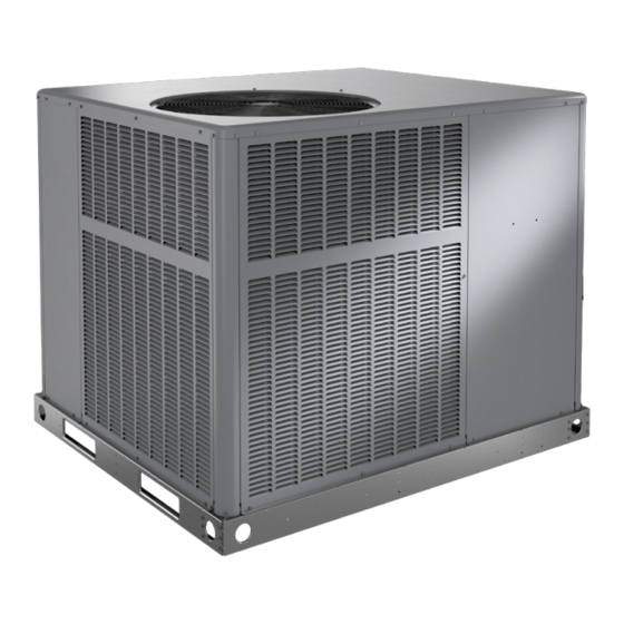
NP14A AND NP14H SERIES UNITS
RESIDENTIAL PACKAGED UNITS
Air Conditioners and Heat Pumps
507296G03
03/2022
Table of Contents
Unit Dimensions ..........................................................2
Roof Curb Dimensions ................................................4
Adjustable Roof Curb Dimensions...............................6
Installation ...................................................................9
Electrical Wiring .........................................................11
Duct System ..............................................................12
Filters .........................................................................12
Condensate Drain......................................................13
Sequence of Operation..............................................13
Maintenance ..............................................................16
Wiring Diagrams ........................................................19
*P507296G03*
CAUTION
Issue 2211
GE Appliances
A Haier Company
Appliance Park
Louisville, KY 40225
(P) 507296G03
Page 1 of 20
Advertisement
Table of Contents

Related Manuals for Armstrong Air NP14A Series


Summary of Contents for Armstrong Air NP14A Series
-
Page 1: Table Of Contents
INSTALLATION AND MAINTENANCE INSTRUCTIONS NP14A AND NP14H SERIES UNITS RESIDENTIAL PACKAGED UNITS Air Conditioners and Heat Pumps 507296G03 03/2022 THIS MANUAL MUST BE LEFT WITH THE Table of Contents HOMEOWNER FOR FUTURE REFERENCE Unit Dimensions ............2 Roof Curb Dimensions ..........4 Adjustable Roof Curb Dimensions.......6 Installation ..............9 WARNING... -
Page 2: Unit Dimensions
Unit Dimensions - Small Base Air Conditioners & Heat Pumps 47.66 2.48 1.98 2.33 2.33 16.77 14.02 RETURN SUPPLY 18.52 11.49 11.49 16.07 TOP VIEW 47.66 POWER ENTRY POWER ENTRY 6.94 3.25 4.56 20.31 21.06 23.19 SIDE VIEWS CONDENSATE 40.89 21.63 DRAIN 3/4 NPT 13.21... - Page 3 Unit Dimensions - Large Base Air Conditioners & Heat Pumps 56.13 2.11 2.39 2.33 2.33 19.49 19.49 RETURN SUPPLY 18.52 11.49 11.49 TOP VIEW 16.07 47.66 POWER ENTRY POWER ENTRY 6.94 3.25 10.06 25.81 26.56 SIDE VIEWS 28.68 44.89 21.63 CONDENSATE DRAIN 3/4 NPT 13.21...
-
Page 4: Roof Curb Dimensions
Roof Curb Dimensions - Small Base Air Conditioners & Heat Pumps 3/4 (19) RETURN Opening for Power Entry OPENING Through Unit Base 5-1/2 x 5-5/8 in. (140 x 31 mm) 16-7/8 44-3/8 (429) (1127) 11-1/2 2-1/8 (287) (54) Insulated Panels 5-3/4 13-7/8 (146) - Page 5 Roof Curb Dimensions - Large Base Air Conditioners & Heat Pumps 3/4 (19) Opening for Power Entry Through Unit Base 5-1/2 x 5-5/8 in. 19-1/2 (140 x 31 mm) 44-3/8 (380) 11-1/2 2-1/8 (1127) (287) (54) RETURN Insulated OPENING Panels 19-1/2 (380) SUPPLY...
-
Page 6: Adjustable Roof Curb Dimensions
Adjustable Roof Curb Dimensions - Small Base Air Conditioners & Heat Pumps (Knock-Down Style) CLIPLOCK CORNER DETAIL Top Edge Wood Nailer Strip CURB PROFILE Bottom Flange Typical Slot Typical Locking Tab NOTE: See Cliplock 1000 installation instructions for complete assembly and installation procedures and requirements. 1-3/4 Opening for Power Line Entry thru base... - Page 7 Adjustable Roof Curb Dimensions - Large Base Air Conditioners & Heat Pumps (Knock-Down Style) CLIPLOCK CORNER DETAIL Top Edge Wood Nailer Strip Bottom Flange CURB PROFILE Typical Slot Typical Locking Tab NOTE: See Cliplock 1000 installation instructions for complete assembly and installation procedures and requirements. 1-3/4 Opening for Power Line Entry thru base...
- Page 8 Adjustable Roof Curb Dimensions - Air Conditioners & Heat Pumps (Welded Style) Front Flange 8 (203) NOTE: Unit Base Rail Minimum Clips (4) Height 4 (102) Built-In Rain Sides and Diverter Back Flange (Not Shown) 6 (152) Built-In Drip Edge Unit Base Rail 3/4 (76) Unit Base Rail...
-
Page 9: Installation
Location The unit is designed to be located outdoors with sufficient WARNING clearance for free entrance to the air inlet and discharge air openings. The location must also allow for adequate Improper installation, adjustment, alteration, service, service access. or maintenance can cause injury or property damage. Refer to this manual. - Page 10 Compressor • The unit operating conditions (including airflow, cooling operation, ignition, input rate, temperature Units are shipped with compressor mountings factory rise and venting) must be verified according to these adjusted and ready for operation. Do not loosen installation instructions. compressor mounting bolts.
-
Page 11: Electrical Wiring
Electrical Wiring CAUTION All field wiring must be done in accordance with National Electrical Code recommendations, local codes, and Before lifting a unit, make sure that the weight is applicable requirements of UL Standards, or in accordance distributed equally on the cables so that it will lift evenly. with Canadian Electrical Code recommendations, local codes, or CSA Standards. -
Page 12: Duct System
Thermostat The supply and return air duct systems should be designed for the CFM and static requirements of the job. They The room thermostat should be located on an inside should not be sized to match the dimensions of the wall where it will not be subject to drafts, sun exposure, duct connections on the unit. -
Page 13: Condensate Drain
Condensate Drain Crankcase Heater (if used) Some models may be equipped with a crankcase heater This package unit is equipped with a 3/4” FPT coupling to prevent excessive migration of liquid refrigerant into the for condensate line connection. Plumbing must conform compressor during off cycles. - Page 14 heater sequencers as well as the indoor blower. Upon satisfying auxiliary heat demand, the thermostat opens DEFROST TIMING PINS (P1) above circuits and heating elements sequence off; blower continues to operate until all heating elements have turned TEST off. PINS DIAGNOSTIC LEDS Defrost System...
- Page 15 At the end of the defrost cycle, when the unit goes The delay is bypassed by placing the timer select jumper back to heating mode, the low pressure switch is across the TEST pins for 0.5 seconds. checked to see if it has reset. If so, the strikeout is not counted.
-
Page 16: Maintenance
System Performance Model Liquid Subcooling +/- 2° This equipment is a self-contained, factory optimized refrigerant system, and should not require adjustments to 2 Ton system charge when properly installed. If unit performance 2.5 Ton is questioned, perform the following checks. 3 Ton Ensure unit is installed per manufacturer’s instructions 3.5 Ton... - Page 17 Condenser Coil Clean condenser coil annually with water and inspect monthly during the cooling season. Condenser coil may need to be cleaned at startup in case oil from the manufacturing process is found on the condenser coil. Table 7. Cooling Performance - AC Models 80 DB / 67 WB Deg.
- Page 18 Table 9. Cooling Performance - HP Models 80 DB / 67 WB Deg. Air Temperature Entering Evaporator Coil, Degree F Return Air Cooling Input Pressure 65° 70° 75° 80° 82° 85° 90° 95° 100° 105° 110° 115° (1000 BTU) Suction Liquid Table 8.
-
Page 19: Wiring Diagrams
Wiring Diagrams Figure 8. Connections Diagram - A/C Constant Torque 507296G03 / 31-5000670 Issue 2211 Page 19 of 20... - Page 20 J1-2 J1-1 J1-3 208V 240V Figure 9. Connections Diagram - Heat Pump Constant Torque Page 20 of 20 Issue 2211 507296G03 / 31-5000670...
Need help?
Do you have a question about the NP14A Series and is the answer not in the manual?
Questions and answers