Advertisement
Quick Links
INSTALLATION AND MAINTENANCE INSTRUCTIONS
These instructions must be read and understood completely before attempting installation.
The equipment covered in this manual is to be installed by trained and experienced
service and installation technicians. Improper installation, modification, service, or use
can cause electrical shock, fire, explosion, or other conditions which may cause personal
injury, death, or property damage. Use appropriate safety gear including safety glasses
and gloves when installing this equipment.
Risk of electrical shock. Disconnect all remote power
supplies before installing or servicing any portion of the
system. Failure to disconnect power supplies can result
in property damage, personal injury, or death.
Installation and servicing of air conditioning equipment
can be hazardous due to internal refrigerant pressure
and live electrical components. Only trained and
qualified service personnel should install or service
this equipment. Installation and service performed by
unqualified persons can result in property damage,
personal injury, or death.
Sharp metal edges can cause injury. When installing
the unit, use care to avoid sharp edges.
506859-01
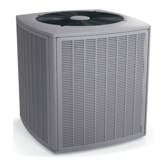
4SCU 16/18LS SERIES
Split System Air Conditioner
WARNING
WARNING
WARNING
WARNING
INSTALLATION ....................................................2
CONNECTION DIAGRAM .....................................4
START-UP ...........................................................14
OPERATION ........................................................17
ALERT CODE ......................................................21
MAINTENANCE ..................................................26
WARRANTY ........................................................31
A Lennox International Inc. Company
*p506859-01*
Issue 1236
TABLE OF CONTENTS
Manufactured By
Allied Air Enterprises, Inc.
215 Metropolitan Drive
West Columbia, SC 29170
*P506859-01*
Page 1 of 32
Advertisement

Related Manuals for Armstrong Air 4SCU 16LS Series


Summary of Contents for Armstrong Air 4SCU 16LS Series
-
Page 1: Table Of Contents
INSTALLATION AND MAINTENANCE INSTRUCTIONS 4SCU 16/18LS SERIES Split System Air Conditioner These instructions must be read and understood completely before attempting installation. WARNING The equipment covered in this manual is to be installed by trained and experienced service and installation technicians. Improper installation, modification, service, or use can cause electrical shock, fire, explosion, or other conditions which may cause personal injury, death, or property damage. -
Page 2: Installation
Inspection of Shipment INSTALLATION Upon receipt of equipment, carefully inspect it for possible shipping damage. If damage is found, it should be noted General on the carrier’s freight bill. Take special care to examine Read this entire instruction manual, as well as the the unit inside the carton if the carton is damaged. - Page 3 Slab Mounting When installing a unit at grade level, install on slab high enough above grade so that water from higher ground will not collect around the unit (See Figure 2). Slab Mounting Figure 2 Roof Mounting Install unit at a minimum of 4” above surface of the roof. Locate the unit above a load bearing wall or area of the roof that can adequately support the unit.
-
Page 4: Connection Diagram
See unit wiring diagram for power supply connections. if the indoor unit is not equipped with a blower relay, one must be field supplied and installed. Do not connect C (common) connection between indoor unit and thermostat except when required by the indoor thermostat. - Page 5 FIELD WIRING & ROUTING - COMMUNICATING CONTROLS Maximum length of wiring (18 gauge) for all connections on the RSBus is 1500 feet (457 meters). Wires should be color coded, with a temperature rating of 95ºF (35ºC) minimum, and solid core (Class II Rated Wiring). All low voltage wiring must enter unit through provided bushing installed in electrical inlet.
- Page 6 Following are some points to consider when placing and 2. Before making line set connections, use dry nitrogen to installing a high-efficiency outdoor unit: purge the refrigerant piping. This will help to prevent oxidation and the introduction of moisture into the Placement system.
- Page 7 If this unit is being matched with an approved line set Installing Refrigerant Line or indoor coil which was previously charged with R-22 During the installation of an air conditioning system, it is refrigerant, the line set and coil must be flushed prior to important to properly isolate the refrigerant line to prevent installation.
- Page 8 Figure 9 Figure 10 Page 8 of 32 Issue 1236 506859-01...
- Page 9 existing system. Refer to the gauges after shutdown Flushing Existing Line Set and Indoor Coil to confirm that the entire system is completely void of This procedure should not be performed on systems refrigerant. Disconnect the liquid and suction lines from which contain contaminants, such as compressor burn the existing outdoor unit.
- Page 10 4. Remove the existing R-22 refrigerant flow control orifice or thermal expansion valve before continuing with flushing procedures. R-22 flow control devices are not approved for use with R-410A refrigerant and may prevent proper flushing. Use a field-provided fitting to reconnect the lines.
- Page 11 3. An R410A system will not operate properly with an R-22 3. Connect the external equalizer line to the equalizer port on the suction line and tighten to 8 ft.lbs. metering device. 4. Strap the superheat sensing bulb to the suction header. Suction Line (Ball Type) Service Valve If installing an expansion valve on an indoor coil that Suction line (ball type) service valves function the same...
- Page 12 3. Open the high pressure side of the manifold to allow R410A into the line set and indoor unit. Weigh in a trace amount of R410A. (A trace amount is a maximum of 2 oz. of refrigerant or 3 lbs. pressure.) Close the valve on the R410A cylinder and the valve on the high pressure side of the manifold gauge set.
- Page 13 3. Connect the vacuum pump (with vacuum gauge) to the center port of the manifold gauge set. 4. Open both manifold valves and start vacuum pump. 5. Evacuate the line set and indoor unit to a minimum of 500 microns or lower. During the early stages of evacuation, it is desirable to close the manifold gauge valve at least once to determine if there is a rapid rise in pressure.
-
Page 14: Start-Up
Units are factory charged with the amount of R410A START-UP refrigerant indicated on the unit rating plate. This charge is based on a matching indoor coil and outdoor coil with 15’ CAUTION line set. For varying lengths of line set, refer to Table 4 for refrigerant charge adjustment. - Page 15 Figure 15 1. Recover the refrigerant from the unit. Measure the liquid line temperature and the outdoor ambient temperature as outlined below: 2. Conduct a leak check, then evacuate as previously 1. Connect the manifold gauge set to the service valve outlined.
- Page 16 R-410A Temperature/Pressure Chart Temp. Pressure Temp. Pressure Temp. Pressure °F Psig °F Psig °F Psig 100.8 214.0 396.0 102.9 217.4 401.3 5. Compare the subcooling value with those shown in Table 105.0 220.9 406.7 6. If subcooling is greater than shown, recover some 107.1 224.4 412.2...
-
Page 17: Operation
OPERATION Outdoor unit and indoor blower cycle on demand from the room thermostat. When the thermostat blower switch is moved to the ON position, the indoor blower operates continuously. 6. Compare the approach value with those shown in Table 7. If the values do not agree with those provided in Table Filter Drier 7, add refrigerant to lower the approach temperature The unit is equipped with a large capacity bi-flow filter... - Page 18 Normal Operating Pressures 1st Stage (Low Capacity) 4SCU16-24 4SCU16-36 4SCU16-48 4SCU16-60 Outdoor Coil Entering Air Temp. °F 2nd Stage (High Capacity) 4SCU16-24 4SCU16-36 4SCU16-48 4SCU16-60 Outdoor Coil Entering Air Temp. °F 1st Stage (Low Capacity) 4SCU18-24 4SCU18-36 4SCU18-48 4SCU18-60 Outdoor Coil Entering Air Temp.
- Page 19 CONTROL BOARD Figure 14 506859-01 Issue 1236 Page 19 of 32...
- Page 20 Operation Seven-Segment Alert and System Status Codes Outdoor unit and indoor blower cycle on demand from the Alert codes are displayed using the seven segment display room thermostat. When the thermostat blower switch is located on the outdoor control. moved to the ON position, the indoor blower operates continuously.
-
Page 21: Alert Code
Seven-Segment Display Alert Codes NO T E - S yste m fa u l t a n d l o cko u t se ve n - se g m e n t d i sp l a y a l a rm co d e s ta ke s p re ce d e n ce o ve r syste m sta tu s co d e s (co o l i n g , h e a ti n g sta g e s o r d e fro st/d e h u m i d i fi ca ti o n ). - Page 22 Table 9. Seven-Segment Display Alert Codes (continued) NOTE: Additional codes may be found in Comfort Sync room thermostat manual. Table 10. Outdoor Control Seven-Segment Unit Status Displays D e s c ription E x a m ple of D is pla y 1 S ta g e A C : 1 A C 2 S ta g e A C : 2 A C 1 S ta g e A C : 1 H P...
- Page 23 Table 10. Outdoor Control Seven-Segment Unit Status Displays (continued) D e s c ription E x a m ple of D is pla y Idle M ode: Dec im al point blink s at 1 Hz (0.5 s ec ond on, 0.5 s ec ond off). Id le M o d e : Dec im al point blink s at 1 Hz Dis play O F F .
- Page 24 * Information will be displayed but does not apply to this product Page 24 of 32 Issue 1236 506859-01...
- Page 25 506859-01 Issue 1236 Page 25 of 32...
-
Page 26: Maintenance
MAINTENANCE Indoor Unit 1. Clean or change filters. WARNING 2. Adjust blower speed for cooling. Measure the pressure drop over the coil to determine the correct blower CFM. Before performing maintenance operations on system, turn the electric power to unit OFF at disconnect 3. - Page 27 HOMEOWNER INFORMATION The outdoor coil may require frequent cleaning, depending on environmental conditions. Clean the outdoor coil with an unpressurized water hose to remove surface contaminants In order to ensure peak performance, your system must be properly maintained. Clogged filters and blocked airflow and debris.
- Page 28 Start-Up and Performance Checklist Job Name _____________________________ Job No. ____________ Date ___________ Job Location ___________________________ City _______________ State ___________ Installer _______________________________ City _______________ State ___________ Unit Model No. _________________________ Serial No._____________________________ Service Technician _______________________ Nameplate Voltage _____________________ Rated Load Ampacity _________ Compressor Amperage ________ Outdoor Fan __________ Maximum Fuse or Circuit Breaker ________________________...
- Page 29 4SCU16LS124-160 Wire Diagram 506859-01 Issue 1236 Page 29 of 32...
- Page 30 4SCU18LS124-160 Wiring Diagram Page 30 of 32 Issue 1236 506859-01...
-
Page 31: Warranty
ALLIED AIR ENTERPRISES EQUIPMENT LIMITED WARRANTY APPLIES IN U.S.A. AND CANADA ONLY FAILURE TO MAINTAIN YOUR EQUIPMENT WILL VOID THIS WARRANTY COVERED EQUIPMENT The following Allied Air Enterprises heating and cooling equipment is covered by the Limited Warranty, Condensing Units: 2SCU13, 4SCU13, 4SCU14, 4SCU16, 4SCU18, 2AC13, 2AC14, 4AC13, 4AC14 Heat Pumps: 2SHP13, 4SHP13, 2SHP14, 4SHP14, 4SHP16, 4SHP18, 2HP13, 2HP14, 4HP13, 4HP14, 4HP16, 4HP18 Gas Furnaces: G1N80, G1D80, G2D80, G1D91, G1D93, G2D93, G2D95, FPBB, CG80, CG90, CG92, CG93, CG95, A97, A96, A95, A952V, A93, A80, 95G2, 95G2V, 95G1, 92G1, 80G2, 80G1 Oil Furnaces: LBR80, LBF80, LHF80, LUF80, LHR80, L83, RLUF, RLBF, RLBR, RLBU, RLHF, RLHR, ODHA, OLFA, OLRA, OUFA... - Page 32 R-22 compressors, and any parts not affecting unit operation. REQUIREMENTS FOR EXTENDED COVERAGE- The unit is an Armstrong Air, AirEase, Ducane, or Concord branded unit; 2. The unit is installed in a residential application, which is an owner-occupied single-family residence. No commercial applications are allowed;...
Need help?
Do you have a question about the 4SCU 16LS Series and is the answer not in the manual?
Questions and answers