Advertisement
This is a safety alert symbol and should never be ignored. When you see this symbol on labels or in
manuals, be alert to the potential for personal injury or death.
Table of Contents
Installation ...................................................................2
Electrical Wiring ...........................................................3
Start-Up .....................................................................11
Operation ...................................................................14
Maintenance ..............................................................20
Homeowner Information ............................................21
Risk of electrical shock. Disconnect all remote power
supplies before installing or servicing any portion of the
system. Failure to disconnect power supplies can result
in property damage, personal injury, or death.
Sharp metal edges can cause injury. When installing
the unit, use care to avoid sharp edges.
Manufactured By
Allied Air Enterprises LLC
A Lennox International, Inc. Company
215 Metropolitan Drive
West Columbia, SC 29170
507607-03
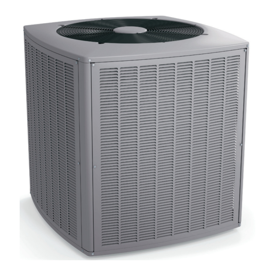
INSTALLATION INSTRUCTIONS
4SCU 16 LS SERIES
Split System Air Conditioner
This manual must be left with the homeowner for future reference.
WARNING
WARNING
Save these instructions for future reference
Installation and servicing of air conditioning equipment
can be hazardous due to internal refrigerant pressure
and live electrical components. Only trained and
qualified service personnel should install or service
this equipment. Installation and service performed by
unqualified persons can result in property damage,
personal injury, or death.
The equipment covered in this manual is to be installed
by trained and experienced service and installation
technicians. Improper installation, modification, service,
or use can cause electrical shock, fire, explosion, or
other conditions which may cause personal injury,
death, or property damage. Use appropriate safety gear
including safety glasses and gloves when installing this
equipment.
*P507607-03*
Issue 1827
WARNING
WARNING
(P) 507607-03
Page 1 of 23
Advertisement

Related Manuals for Armstrong Air 4SCU 16 LS Series


Summary of Contents for Armstrong Air 4SCU 16 LS Series
-
Page 1: Table Of Contents
INSTALLATION INSTRUCTIONS 4SCU 16 LS SERIES Split System Air Conditioner This manual must be left with the homeowner for future reference. This is a safety alert symbol and should never be ignored. When you see this symbol on labels or in manuals, be alert to the potential for personal injury or death. -
Page 2: Installation
Check the unit rating plate to confirm specifications are as Installation ordered. Location of Unit General Outdoor units operate under a wide range of weather Read this entire instruction manual, as well as the conditions; therefore, multiple factors must be considered instructions supplied in separate equipment, before when positioning the unit. -
Page 3: Electrical Wiring
Roof Mounting using a proper conduit fitting. Units are approved for use only with copper conductors. 24V Class II circuit Install unit at a minimum of 4” above surface of the roof. connections are made in the low voltage junction box. Locate the unit above a load bearing wall or area of the Refer to Figure 3 for high voltage field wiring diagram. - Page 4 Install room thermostat on an inside wall that is not subject to drafts, direct sunshine, or other heat sources. Install low voltage wiring from outdoor to indoor unit and from thermostat to indoor unit (Figure 15). Do not bundle any excess 24V control wire inside control box. Run control wire through installed wire tie and tighten wire tie to provide low voltage strain relief and to maintain separation of field-installed low and high voltage circuits.
- Page 5 Line Set Isolation Install the thermal expansion valve which is sold separately and which is approved for use with R410A The following illustrations demonstrate procedures that refrigerant in the liquid line at the indoor coil (see ensure proper refrigerant line set isolation. Figure 7 shows Refrigerant Metering Device section).
- Page 6 To hang line set from joist or rafter, use either metal strapping material Wire Tie or anchored heavy nylon wire ties. (around vapor line only) 8’ Strapping Material Floor Joist or (around vapor line only) Roof Rafter Tape or Wire Tie 8’...
- Page 7 Figure 9. Refrigerant Line Sets : Installing Vertical Runs Figure 10. Flushing Connections 507607-03 Issue 1827 Page 7 of 23...
- Page 8 Flushing Existing Line Set and Indoor Coil Remove the existing R-22 refrigerant flow control orifice or thermal expansion valve before continuing This procedure should not be performed on systems which with flushing procedures. R-22 flow control devices contain contaminants, such as compressor burn out. are not approved for use with R-410A refrigerant and Required Equipment may prevent proper flushing.
- Page 9 existing fixed orifice. Failure to remove a fixed orifice when installing an expansion valve to the indoor coil will result in improper operation and damage to the system. Manifold Gauge Set Manifold gauge sets used with systems charged with R410A refrigerant must be capable of handling the higher system operating pressures.
- Page 10 Leak Testing After the line set has been connected to the indoor and WARNING outdoor units, the line set connections and indoor unit must be checked for leaks. Refrigerant can be harmful if inhaled. Refrigerant must always be used and recovered responsibly. Incorrect or irresponsible use of refrigerant can result in personal injury or death.
-
Page 11: Start-Up
Start-Up WARNING Do not use a compressor to evacuate a system. Avoid deep vacuum operation. Extremely low vacuums can CAUTION cause internal arcing and compressor failure. Danger of If unit is equipped with a crankcase heater, it should equipment damage. Damage caused by deep vacuum be energized 24 hours before unit start-up to prevent operation will void warranty. - Page 12 When the heating demand has been satisfied, switch Oz. Per 5 ft. Adjust from 15 Liquid Line Set Diameter the thermostat to cooling mode with a set point of ft. Line Set* 68°F. When pressures have stabilized, use a digital 3/8 in.
- Page 13 Attach high pressure gauge set and operate unit for that the system is overcharged. Pressures lower than several minutes to allow system pressures to stabilize. those listed indicate that the system is undercharged. Verify adjusted charge using the approach method. Compare stabilized pressures with those provided in the charge tables on inside control box cover.
-
Page 14: Operation
addition, the diagnostic LEDs will indicate a locked-out Operation pressure switch after the fifth occurrence of an open pressure switch. Outdoor unit and indoor blower cycle on demand from The unit will remain locked out until power to the board the room thermostat. - Page 15 Seven-Segment Display Alert Codes Code Diagnostic Codes / Status of Equipment Action Required to Clear and Recover E105 Device communication problem - No other devices on RS Equipment is unable to communicate. Indicates numerous BUS (Communication system). message errors. In most cases, errors are related to electrical noise.
- Page 16 Code Diagnostic Codes / Status of Equipment Action Required to Clear and Recover E411 The low pressure switch has opened 5 times during one Open low pressure switch error count reached 5 strikes. The cooling cycle. As a result, the system will shut down. low pressure switch for R410A will open at 40 PSIG and close at 90 PSIG.
- Page 17 Code Diagnostic Codes / Status of Equipment Action Required to Clear and Recover E420 The heat pump defrost cycle has taken more than 20 Defrost cycle lasts longer than 20 minutes. This alarm is minutes to complete. applicable with non-communicating heat pump system only. Check heat pump defrost operation.
- Page 18 Mode Description Example of Display Middle line shall blink at 1 Hz for 2 seconds, followed by a two-second Anti-Short Cycle display of the rounded up number of minutes left in the timer (two Delay minutes, one second shall be displayed as “3”). The Anti-Short Cycle Delay time remaining is displayed when the delay is active.
- Page 19 Error Code Recall Mode (NOTE: control must be in Idle mode) To enter error code recall mode, push and hold button until solid appears, then release button. Control Solid E000 will display up to 10 error codes stored in memory. If is displayed, there are no stored error codes.
-
Page 20: Maintenance
Configuring Unit Capacity (NOTE: Control must be in Idle mode) Release push button - Allows user to select Unit Capacity. IMPORTANT: Field replacement control Solid may need to be manually configured to validate outdoor unit capacity. Refer to unit nameplate model number for capacity in 1,000 of BTUs. -
Page 21: Homeowner Information
Homeowner Information In order to ensure peak performance, your system must Some systems are equipped with an electronic air cleaner, be properly maintained. Clogged filters and blocked airflow designed to remove the majority of airborne particles from prevent your unit from operating at its most efficient level. the air passing through the cleaner. - Page 22 Start-Up and Performance Checklist Job Name: ______________________________________________ Job No. _________________ Date: ________________ Job Location: ____________________________________________ City: ____________________ State: ________________ Installer: ________________________________________________ City: ____________________ State: ________________ Unit Model No. ___________________________________________ Serial No. _______________________________________ Service Technician: _______________________________________ Nameplate Voltage: _______________________________ Rated Load Ampacity: _______________ Compressor Amperage: _________________ Outdoor Fan: _____________________ Maximum Fuse or Circuit Breaker: ____________________________ Electrical Connections Tight?
- Page 23 Figure 15. 4SCU16LS124, 36, 48, 60 Wiring Diagram 507607-03 Issue 1827 Page 23 of 23...
Need help?
Do you have a question about the 4SCU 16 LS Series and is the answer not in the manual?
Questions and answers
can a conventional 2 stage t-stat be hooked and do away with communicating t-stat