Table of Contents
Advertisement
Quick Links
Bridge Navigational Watch Alarm System (BNWAS) X150
X150
BRIDGE NAVIGATIONAL WATCH ALARM SYSTEM
(BNWAS)
User Manual
© This Manual and the information contained therein is the property of AMI Marine Ltd.
It must not be reproduced or otherwise disclosed without prior consent in writing from AMI Marine Ltd
0801 X150 BNWAS User Manual - Iss02
Advertisement
Table of Contents

Related Manuals for AMI Marine X150


Summary of Contents for AMI Marine X150
- Page 1 User Manual © This Manual and the information contained therein is the property of AMI Marine Ltd. It must not be reproduced or otherwise disclosed without prior consent in writing from AMI Marine Ltd 0801 X150 BNWAS User Manual - Iss02...
- Page 2 BNWAS150 - Bridge Navigational Watch Alarm System This Page Intentionally Blank Page 1 of 21...
- Page 3 Brief Record of Change and Reason for Change Iss02 13.09.17 Original Issue NOTE: All alterations must be verified by re-authorisation and approval of the complete document. AMI MARINE LTD Unit 9, Crosshouse Centre Crosshouse Road Southampton SO14 5GZ United Kingdom...
- Page 4 BNWAS150 - Bridge Navigational Watch Alarm System This page Intentionally Blank Page 3 of 21...
- Page 5 This manual is for informational use only, and may be changed without notice. This manual should not be construed as a commitment of AMI Marine Ltd. Under no circumstances does AMI Marine Ltd assume any responsibility or liability for any errors or inaccuracies that may appear in this document. The equipment should only be used for the purposes intended by the manufacturer;...
- Page 6 BNWAS150 - Bridge Navigational Watch Alarm System This page Intentionally Blank Page 5 of 21...
-
Page 7: Table Of Contents
BNWAS150 - Bridge Navigational Watch Alarm System CONTENTS - BNWAS 150 System Overview ..................8 - BNWAS 150 Controls and Functions ................10 - Software Setup and Operation ..................12 Switching On The BNWAS 150 ................12 Entering Setup ....................... 13 Mode Selection ...................... - Page 8 BNWAS150 - Bridge Navigational Watch Alarm System This page Intentionally Blank Page 7 of 21...
-
Page 9: Bnwas 150 System Overview
LCD display. These might include RADAR or ECDIS. External valid reset inputs must be approved by the appropriate approval body before being used. AMI Marine (UK) Ltd will assist with recommendations wherever possible from previous experience but will not accept responsibility if not accepted. - Page 10 BNWAS150 - Bridge Navigational Watch Alarm System Wheel house / Bridge Equipment - Control display, Stage 1 Alarm sounders, Alarm Beacon, Directional PIR’s, and push button reset switches. Push buttons can be mounted on the Bridge wing, and are IP rated accordingly. Accommodation Decks Equipment - Stage 2 Alarms are located in the accommodation area.
-
Page 11: Bnwas 150 Controls And Functions
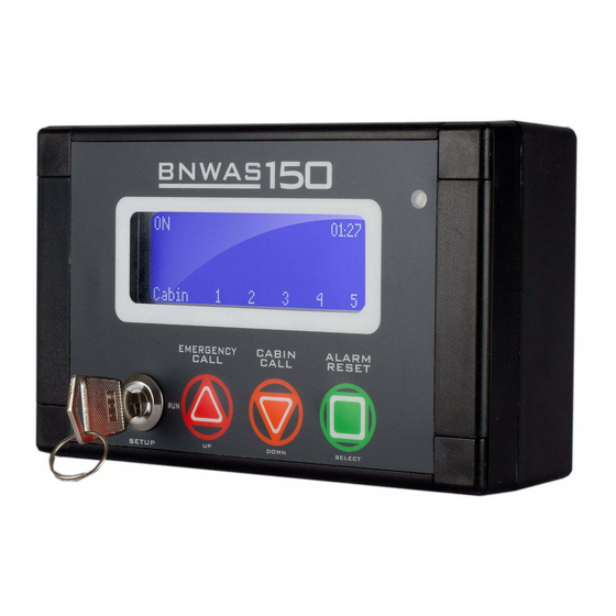
- BNWAS 150 Controls and Functions X150-D Display and Control The BNWAS X150-D Display Control Panel is the user interface and display for the BNWAS150 The display control panel is to be mounted at a suitable location within the ship bridge preferably at a... - Page 12 The X150-SD alarm sounders are used for the 2 or 3 stage alarms and have adjustable volume between 85 and 105dB. The X150-SB performs the same function but also has a highly visible LED indication. Figure 4 – X150-SD Figure 5 – X150-SD...
-
Page 13: Software Setup And Operation
BNWAS150 - Bridge Navigational Watch Alarm System - Software Setup and Operation Switching On The BNWAS 150 SETUP Menu The SETUP mode allows the user to access the SETUP MENU and customise the timing parameters within the BNWAS 150 menus. To enter the SETUP mode insert the key and turn clockwise to SETUP. -
Page 14: Entering Setup
BNWAS150 - Bridge Navigational Watch Alarm System BNWAS150 Startup On first power up a message from the system designers will Designed and built appear on the display. AMI Marine In Great Britain The software version and date will then be displayed followed by V 1.00 10/11/11 CPU 1 and CPU 2 running a self-test, a short beep will be heard on completion. -
Page 15: Mode Selection
BNWAS150 - Bridge Navigational Watch Alarm System Mode Selection Pressing the SELECT button again, will change Dormant 03 : 00 Period SETUP If the key is now turned to the RUN position and removed, the Cabin _ 3 _ _ system is now in the ON mode. -
Page 16: Operational Sequence
BNWAS150 - Bridge Navigational Watch Alarm System Operational Sequence When the BNWAS countdown reaches 00 : 00 STAGE 00 : 00 message will appear. ALARM STAGE ALARM The display and the remote reset buttons will now flash. To reset the system press the RESET button or press a Cabin _ 3 _ _... -
Page 17: Selecting Duty Cabins And Using Cabin Call
BNWAS150 - Bridge Navigational Watch Alarm System Selecting Duty Cabins and Using Cabin Call Selecting Duty Cabins for Stage 2 Alarm The Selecting and De-selecting Cabins function can only be accessed when the system is in MODE. Press and hold the SELECT button until appears. -
Page 18: External Reset
BNWAS150 - Bridge Navigational Watch Alarm System External Reset (if external equipment connected) message will be shown when the RADAR is in RADAR RESET 03 : 00 use by an operator and the BNWAS timer will reset. RADAR RESET (This will only be shown if the RADAR in use connection is made) Cabin _ 3 _ _ message will be shown when the ECDIS is in... -
Page 19: Unacknowledged Alarms
BNWAS150 - Bridge Navigational Watch Alarm System Unacknowledged Alarms (if external equipment connected) This will be displayed if an unacknowledged RADAR ALARM. 00 : 00 alarm is received from the Radar. STAGE ALARM 2 Pressing the RESET button will display any other active RADAR ALARM alarms but will not reset the alarm. -
Page 20: System Faults
BNWAS150 - Bridge Navigational Watch Alarm System - System Faults Power Error If the main power fails the standby power will be used to power the system. This is indicated by the MAIN POWER FAIL being displayed on the LCD screen until the main power is restored to the system. will be shown if the main power input MAIN POWER FAIL 0 1 : 27... -
Page 21: Maintenance Guide
BNWAS150 - Bridge Navigational Watch Alarm System - Maintenance guide The BNWAS 150 system requires periodic (annually) confirmation that all sensors are active, and conduct a full system integrity check. Any damaged/inactive peripherals MUST be replaced by a suitable spare part by an approved engineer. All cabling and interfaces should be re-checked to confirm system integrity and any damaged cables must be replaced/re-wired if required by an approved engineer.
Need help?
Do you have a question about the X150 and is the answer not in the manual?
Questions and answers