
Subscribe to Our Youtube Channel
Related Manuals for Crane KROMBACH TUFSEAT Performance Series


Summary of Contents for Crane KROMBACH TUFSEAT Performance Series
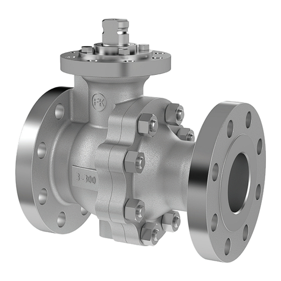
- Page 1 INSTALLATION, OPERATION AND MAINTENANCE MANUAL Floating Ball Design KROMBACH TUFSEAT™ ® Performance Series Ball Valves TUFSEAT by KROMBACH - THE SUPERIOR MSBV www.cranecpe.com...
-
Page 2: Area Of Application
Installation, Operation & Maintenance ATTENTION 1. General Caution! Valves have dead spaces where residue (under pressure) can remain after the flow medium has been 1.1 Area of Application emptied. This operating manual applies for ball valves produced by Friedrich Krombach GmbH Armaturenwerke. ATTENTION The operating manual also applies to identical valves from The same safety requirements apply to valves as to the... - Page 3 Installation, Operation & Maintenance 2. Product 1.3.3 CE Designation Valves that are subject to CE marking are marked additionally by: 2.1. Proper Use • CE mark The valves have been designed exclusively for installation • Code of the issuing office into a pipeline system to block off or guide through media.
-
Page 4: Installation In The Pipeline
Installation, Operation & Maintenance 2.2 Installation in the Pipeline ATTENTION Make sure that valves that have been operated at 2.2.1 General Instructions operating temperatures of > 50°C or < 20°C and the • Before installation in the pipeline, the valve must pipeline connections cannot be touched by the operator, be checked to make sure that it matches the in order to protect the operator from injury. -
Page 5: Maintenance And Testing
Installation, Operation & Maintenance 2.4 Maintenance and Testing ATTENTION Where liquid media with great strain on the body and 2.4.1 Maintenance Interval cover under pressure. Heat expansion and temperature Depending on the type of system and operating data fluctuations are used in the system. Impermissibly high involved, the valve will need some maintenance. - Page 6 Installation, Operation & Maintenance 2.4.4 Body gaskets and packing • The direction of rotation Check the sealing elements for tightness. If they are not (clockwise = CLOSE; leakproof, tighten with the valve depressurised. If tight- anti-clockwise = OPEN) ness is not achieved, a new body gaskets and packing remains the same whether the valve is actuated by must be used.
-
Page 7: Maintenance
IN THIS MANUAL CAN CAUSE FATALITIES, INJURY OR PROPERTY DAMAGE. Maintenance All KROMBACH TUFSEAT Performance Series ball valves This document and other information from Krombach stem seals are adjusted and factory tested for tight shut- contain product or system options for further investigati- off, normally no further adjustment is necessary. - Page 8 Torques Body joint bolting torques, Table-A Class 150 Class 300 Valve Size Bolt QTY Bolt size Bolt Torque Valve Size Bolt QTY Bolt size Bolt Torque (inch) (DN) (no’s) (inch) (Nm) (In-lbs) (inch) (DN) (no’s) (inch) (Nm) (In-lbs) ½” DN15 5/16”-18UNC ½”...
-
Page 9: Stem Seal Adjustment
Stem Seal Adjustment STEM SEAL ADJUSTMENT (Threaded Packing Gland) Note: If a tight seal cannot be obtained, continue with the Sizes: 1/2”-2” Cl.150 & 300, 3” Cl.150 (1156, 1176) instructions for valve repair. To adjust for leakage along the valve stem, turn the Threaded Packing Gland (#8) clockwise in approximately 1/3- turn increments to compress the packing (#13). - Page 10 Stem Seal Adjustment STEM SEAL ADJUSTMENT (Bolted Packing Gland) Sizes: gland (#8) and packing (#13). Use torques from following 3” Cl.300, 4”-6” Cl.150 & 300 (1156, 1176) table. (When tightening packing bolts, use proper crisscross adjustment pattern as shown below). To adjust for leakage along the valve stem, turn the packing adjustment bolts (#21) (6pcs or 8pcs) clockwise, in Note: If a tight seal cannot be obtained, continue with the...
- Page 11 Exploded View Floating Ball Design Standard Trim Floating Ball Design Carbon Steel Stainless Steel Item Quantity Description ASTM ASTM Body A216 WCB 1.0619 A351 CF8M 1.4408 Tail A216 WCB 1.0619 A351 CF8M 1.4408 Ball A182 F316L+coating 1.4404+coating A182 F316L+coating 1.4404+coating Stem A276 Gr.431 1.4057...
- Page 12 6” class 300 floating ball design with key connection item 16 * Quantities may differ depending on the valve size Izdelal Pregledal Videl Merilo Datum ARMATURE d.o.o. Izdelal CRANE Koroška cesta 55 Pregledal SI-2366 Muta / Slovenija Videl Objekt: Merilo Načrt Št.: Floating Design, Ball valve, 2-piece bare stem Izdelan iz: NPS3 Class300 High Temp.
- Page 13 Assembly and Disassembly Instructions DIS-ASSEMBLY ATTENTION If lifting tools (for example ropes) are necessary to carry the valve to the workshop the actuator should be free from heavy load and the valve and actuator must not be damaged. ATTENTION For shut-off valves with single-acting drives, the drive must be in the safety position for reasons of safety in order to exclude accidental switching during installation.
- Page 14 Assembly of KFO-1176 Standard Trim Floating Ball Valve KFO1176: Standard Trim Stem #4 Guide Bushing #14 Packing Gland #8 Packing #13 Support Ring #9 Spring Energized Lip seal #12 SX Stem Seal #7 Figure 5 1. Apply castrol optimal paste on short threaded part of the 3.
- Page 15 Assembly of KFO-1176 Standard Trim Floating Ball Valve 6. Install one number of ‘Graphite packing ring (thick)’ & 9. Compress the packings to the assembly compression; ‘Diffusion barrier ring (thin) (#13) over the Stem (#4). Tighten the screws incrementally to the torque specified on the table from Page 9 or 10.
- Page 16 Assembly of KFO-1176 Standard Trim Floating Ball Valve Seat Assembly of KFO-1176 (Standard Trim Floating Ball Valve) 17. Using a press, apply pressure on the seat "b" (#6) to pre- Figure 6 compress the seat seal. Use a plastic spacer to protect the seat and apply specified pressure.
- Page 17 Assembly of KFO-1176 Standard Trim Floating Ball Valve pattern at least three (3) times to assure proper and uniform torque. NOTE: When the valve is re-assembled, be sure the studs protrude through the nut a minimum of one (1) thread. 20.
- Page 18 Assembly of KFO-1156 High Temperature Trim Floating Ball Valve KFO1156: High Temperature Trim 4. Install one number of graphite packing ring (thick) & diffusion barrier ring (thin) (#13) over the stem (#4). 1. Apply Castrol Optimal paste on short threaded part of the Studs (#10) and insert them into the Body tap holes.
- Page 19 Assembly of KFO-1156 High Temperature Trim Floating Ball Valve 10. Repeat steps 4, 5, 6, 7 & 8, to get the stack of 8 packing rings; alternate 4 Graphite packing rings (thick) & 4 Diffusion barrier rings (thin). 11. Install the Threaded Packing Gland (#8) over the valve stem: 11.1 Threaded packing gland sizes: 1/2”-2”...
- Page 20 Assembly of KFO-1156 High Temperature Trim Floating Ball Valve 14. Insert S-ring (#42) into the body part (#1) over the wave spring (#41). Keep orientation of S-ring as shown in Fig.9. 15. Insert seal ring (#40) over seat "B" (#6) and insert the two together into the valve cover or tail (#2).
- Page 21 Assembly of KFO-1156 High Temperature Trim Floating Ball Valve 19. Install spiral wound body gasket (5) in the groove of the body . 4-bolts 8-bolts 20. Join the body (#1) and tail (#2), (lettering on the halves face the same direction), Install and tighten the body stud nuts in the crossing pattern shown in figure 7.
- Page 22 Instructions for Mounting Hand Lever and Locking Device NPS ½” CL150&300 to 4” CL150 (KFO1156, 1176) 1. Insert and tighten both “stop pins” (2pcs) as shown in Figure 2. ATTENTION Do not over tighten Stop Pin. Excessive torque may fracture screw and could result in minor injury or property damage! Size M6 thread, max bolt torque= 54 in-lbs or 6 Nm Size M10 thread, max bolt torque=248 in-lbs or 28 Nm...
- Page 23 Hand lever ear Stem flats Stem mm shank Hand lever Locking plate Hex nut Hole for SHC screw Hand lever ear Socket Head Cap Screw (SHCS) Stem flats Instructions for Mounting Hand Lever and Locking Device Socket Head Cap Screw (Stop pin) Hex nut Stem Locking plate...
- Page 24 Crane Co., and its subsidiaries cannot accept responsibility for possible errors in catalogues, brochures, other printed materials, and website information. Crane Co. reserves the right to alter its products without notice, including products already on order provided that such alteration can be made without changes being necessary in specifications already agreed.
Need help?
Do you have a question about the KROMBACH TUFSEAT Performance Series and is the answer not in the manual?
Questions and answers