
Related Manuals for Crane KROMBACH 510


Summary of Contents for Crane KROMBACH 510
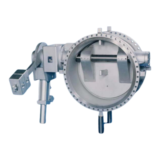
- Page 1 Operating and Maintenance Instructions TILTING DISC TYPE CHECK VALVES TYPE 510 with lamellar sealing Tilting Disc Type Check Valves Operations Manual No.: 04 / 2005 BUW-510/1-E...
-
Page 2: Table Of Contents
TABLE OF CONTENTS INTRODUCTION ................... 2 INTENDED USE ..................2 SAFETY INSTRUCTIONS ..............2 3.1..................2 ENERAL SAFETY INSTRUCTIONS 3.2..............2 AFETY INSTRUCTIONS FOR THE OPERATOR 3.3......................3 PECIAL HAZARDS LABELLING OF THE TILTING DISC TYPE CHECK VALVES ....4 TRANSPORT AND STORAGE .............. -
Page 3: Introduction
1. Introduction This manual is intended to support users of tilting disc type check valves in installation, operation and maintenance. If the following attention and warning notices are not followed, danger could result, and the manufacturer’s guarantee could become ineffective. Please contact KROMBACH in case of any questions. -
Page 4: Special Hazards
It must be ensured that the materials selected for the parts of the armature that come into contact with the medium are suitable for the media used. KROMBACH accepts no liability for damage which results from corrosion caused by aggressive media. -
Page 5: Labelling Of The Tilting Disc Type Check Valves
4. Labelling of the tilting disc type check valves Every check valve bears a label containing the following information on the type plate. Labelling Comment Manufacturer KROMBACH GmbH & Co. KG Material E.g. 1.4408 = casing material = consecutive production no. - year of Factory No. -
Page 6: Installation Into The Pipeline
6. Installation into the pipeline 6.1. General The same instructions apply for the installation of armatures into a pipeline as for the connections of pipes and similar elements of the pipeline. For armatures, the following instructions apply additionally. Section 5 must also be observed for transportation to the installation site. Butterfly valves must be transported and installed with the valve disc closed. -
Page 7: Installation Position And Direction Of Flow
6.3. Installation position and direction of flow ⇒ The check valve has to be mounted so that the arrow on the valve body coincides with the expected flow direction through the pipe. ⇒ The check valve has to be mounted with horizontal located shaft. 6.4. -
Page 8: Pressure Testing And Commissioning
All check valves: Protective grating for lever and weight and if necessary for the oil brake has to be mounted. Danger to life ⇒ With operating temperatures above 200°C, the valve casing must be insulated such that the temperature difference between the housing and the valve disc is not more than 100°C. ⇒... -
Page 9: Troubleshooting Guide
9. Troubleshooting guide It is essential to observe the Safety Instructions in Section 3 when rectifying faults. Nature of fault Action Tighten screws. If this does not rectify the leakage: Leakage on the bearing cover repair may be necessary - replace gasket. Observe the instructions in Section 3.3 “Special hazards”. -
Page 10: Drawings
10. Drawings 10.1. List of parts Item Designation Item Designation Body Stuffing box Body-seat Stud bolt with nut Disc 18.1 Option:belleville spring Retainer flange Packing Hex. head screw 20.1 End plate Spring washer 20.2 Cover Tapered pin 20.3 Lever Plug 20.4 Weight Gasket... -
Page 11: Detail Drawing >Tilting Disc Type Check Valve< With Flanges
10.2. Detail Drawing >Tilting Disc Type Check Valve< with Flanges Drawing does not contain any order related special oil brake positions or mounting positions. Tilting Disc Type Check Valves Date: 22.03.2005 Operating instruction No.: prepared: C.Wied approved: H.Six BUW-510/1-E Page: 10 of 14... -
Page 12: Detail Drawing >Tilting Disc Type Check Valve< With Welding Ends
10.3. Detail Drawing >Tilting Disc Type Check Valve< with welding ends Drawing does not contain any order related special oil brake positions or mounting positions. Tilting Disc Type Check Valves Date: 22.03.2005 Operating instruction No.: prepared: C.Wied approved: H.Six BUW-510/1-E Page: 11 of 14... -
Page 13: Repair Instructions
11. Repair instructions 11.1. General ⇒ For selection of the correct detail drawing see Section 10.2 or 10.3. ⇒ For parts list, see Section 10.1. ⇒ All information from the type plate must be given when ordering replacement parts. Only original KROMBACH parts may be installed. -
Page 14: Replacing The Lamellar Sealing
11.3.7. Put on the end plate (20.1) and mount the keys (20.3) and lever (20.9). Do not use force to mount the end plate or the lever on the valve shaft! The assembly should take place smoothly. Important 11.3.8. First tighten the packing nuts (18) equally. 11.3.9. - Page 15 After that the sealing element hast to be fastened again. Friedrich Krombach GmbH Armaturenwerke | Marburger Str. 364 | 57223 Kreuztal www.krombach.com Tel: +49-2732-520 00 | Fax: +49-2732-520 100 www.craneenergy.com • • CRANE Energy Flow Solutions | ONE TEAM ENERGIZED TO WIN Tilting Disc Type Check Valves Date: 22.03.2005 Operating instruction No.:...
Need help?
Do you have a question about the KROMBACH 510 and is the answer not in the manual?
Questions and answers