
Related Manuals for Heinner HDU-M10


Summary of Contents for Heinner HDU-M10
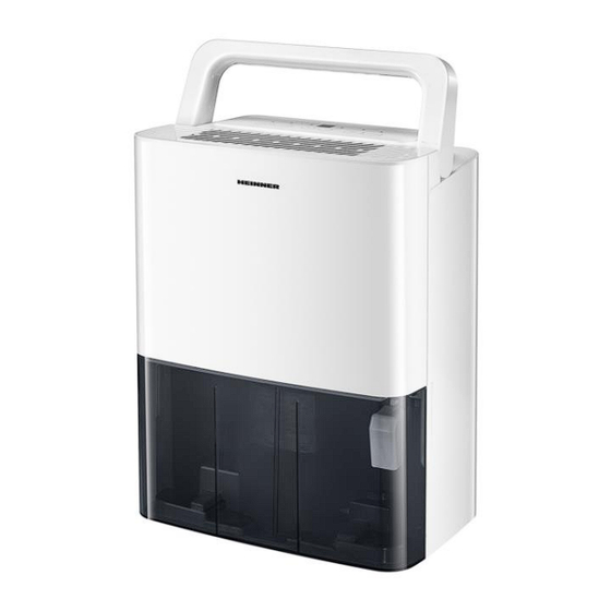
- Page 1 DEHUMIDIFIER Model: HDU-M10 Dehumidifier Dehumidifying capacity: 10L Color: white...
-
Page 2: Package Contents
Thank you for chosing this product! INTRODUCTION Please read this instruction manual carefully before using it and keep it for later informat This manual is conceived for ofering you all of the necessary info regarding instalation, using and maintenance of the machine. For a correctly and safely use of the machine, please, read this manual before instalation and using. -
Page 3: Safety Precautions
III. SAFETY PRECAUTIONS To prevent injury to the user or other people and property damage, the following instructions must be followed. Incorrect operation due to ignoring of instructions may cause harm or damage. This symbol indicates that ignoring instructions may cause death or serious injury. - Page 4 CAUTION 13. Do not use the unit in small spaces. Lack of ventilation can cause overheating and fire. 14. Do not put in places where water may splash onto the unit. 15. Place the unit on a level, sturdy section of the floor.
- Page 5 IV. WARNING FOR USING R32/R290 REFRIGERANT Do not use means to accelerate the defrosting process or to clean, other than those recommended by the manufacturer. The appliance shall be stored in a room without continuously operating ignition sources (for example: open flames, an operating gas appliance or an operating electric heater).
- Page 6 Explanation of symbols on the unit (For R32/R290 refrigerant only): This symbol shows that this appliance used a flammable WARNING refrigerant. If the refrigerant is leaked and exposed to an external ignition source, there is a risk of fire.
- Page 7 Checking for presence of refrigerant The area shall be checked with an appropriate refrigerant detector prior to and during work, to ensure the technician is aware of potentially flammable atmospheres. Ensure that the leak detection equipment being used is suitable for use with flammable refrigerants, i.e.
- Page 8 Checks to electrical devices Repair and maintenance to electrical components shall include initial safety checks and component inspection procedures. If a fault exists that could compromise safety, then no electrical supply shall be connected to the circuit until it is satisfactorily dealt with. If the fault cannot be corrected immediately but it is necessary to continue operation, an adequate temporary solution shall be used.
- Page 9 Detection of flammable refrigerants Under no circumstances shall potential sources of ignition be used in the searching for or detection of refrigerant leaks. A halide torch (or any other detector using a naked flame) shall not be used.
- Page 10 Ensure that the refrigeration system is earthed prior to charging the system with refrigerant. Label the system when charging is complete (if not already). Extreme care shall be taken not to overfill the refrigeration system. Prior to recharging the system it shall be pressure tested with OFN.
- Page 11 Recovery When removing refrigerant from a system, either for servicing or decommissioning, it is recommended good practice that all refrigerants are removed safely. When transferring refrigerant into cylinders, ensure that only appropriate refrigerant recovery cylinders are employed. Ensure that the correct number of cylinders for holding the total system charge is available.
- Page 12 IDENTIFICATION PARTS NOTE: All the illustrations in the manual are for explanation purpose only. Your machine may be slightly different. The actual shape shall prevail. The unit can be controlled by the unit control panel alone or with the remote controller. This manual does not include Remote Controller Operations, see the <<Remote Controller Instruction>>...
- Page 13 Handle Control panel Air intake grille Air intake grile Drain hose outlet Air filter (behind the grille) Power cord band (used only when storing the unit) Bucket Water level window Power cord Power plug Handle Control panel Air intake grille...
-
Page 14: Positioning The Unit
POSITIONING THE UNIT A dehumidifier operating in a basement will have little or no effect in drying an adjacent enclosed storage area, such as a closet, unless there is adequate circulation of air in and out of the area. - Page 15 When using the unit When first using the dehumidifier, operate the unit continuously 24 hours. This unit is designed to operate with a working environment between 5˚C and 35°C. If the unit has been switched off and needs to be switched on again quickly, allow approximately three minutes for the correct operation to resume.
- Page 16 Indicator Function Indicator Function Continuous dehumidifying Continuous operation mode light indicator light Bucket full indicator light 40% humidity level setted mode operation on indicator light Power light 50% humidity level setted mode operation on indicator light Auto defrost indicator light...
- Page 17 Power button Press to turn the dehumidifier on and off. Note: The power light illuminates when the unit is switched on and turns dark when the unit is switched off. When Humidity/Temperature sensor malfunction occurs, the power light blinks at 5 times per second (on some models).
- Page 18 Mode/ button Press to select the operation mode: consitnuously dehumidification – 40% humidity level – 50% humidity vele – 60% humidity level continuously dehumidification Display (On some models) Shows the set % humidity level from 35% to 85% or auto start/stop time (0~24) while setting, then shows the actual (±5% accuracy) room % humidity level in a...
-
Page 19: Removing The Collected Water
VII. REMOVING THE COLLECTED WATER There are two ways to remove collected water. 1. Use the bucket When the unit is off, if the bucket is full, the unit will beep 8 times and the Full indicator light will flash, the digital display shows P2. - Page 20 Remove the rubber plug Insert the water hose from the drain outlet 1. Pull out the bucket a little. 2. Hold both sides of the bucket with even strength and pull it out from the unit. Pour the water out.
- Page 21 Pull out the bucket a little. Do not blow water fow by a rise. Do not block water flow by a retortion. Make sure the water hose is lower than the drain hose. Note: When the continuous drain feature is not being used, remove the drain hose from the outlet and attach the rubber...
-
Page 22: Care And Cleaning Of The Dehumidifier
VIII. CARE AND CLEANING OF THE DEHUMIDIFIER Turn the dehumidifier off and remove the plug from the wall outlet before cleaning. 1. Clean the Grille and Case Use water and a mild detergent. Do not use bleach or abrasives. - Page 23 Grip the tab on the filter and press it in slightly to take it out from the filter holder for model A. take out the right and left filters for the model B. Grip the tab on the filter and press them in.
- Page 24 Note: The cabinet and front may be dusted with an oil-free cloth or washed with a cloth dampened in a solution of warm water and mildliquid dishwashing detergent. Rinse thoroughly and wipe dry. Never use harsh cleansers, wax or polish on the cabinet front. Be sure to wring excess water from the cloth before wiping around the controls.
-
Page 25: Troubleshooting Tips
TROUBLESHOOTING TIPS Before installing for service, review the chart below first yourself Problem What to check Unit does not start Make sure the dehumidifier s plug is pushed completely into the outlet. Check the house fuse/circuit breaker box. Dehumidifier has reached its preset level or bucket is full. -
Page 26: Technical Data
TECHNICAL DATA HDU-M10 Power 340W Voltage 220-240V, 50Hz Moisture Removal 10L/24H Capacity Color White Environment friendly disposal You can help protect the environment! Please remember to respect the local regulations: hand in the non-working electrical equipment’s to an appropriate waste disposal center.
Need help?
Do you have a question about the HDU-M10 and is the answer not in the manual?
Questions and answers