
Related Manuals for SAF-HOLLAND SK-V 20


Summary of Contents for SAF-HOLLAND SK-V 20
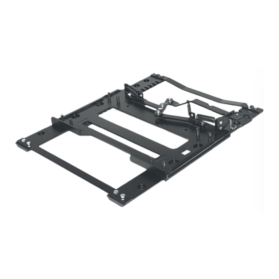
- Page 1 Aufbau - Bedienung - Wartung Mounting - Operation - Maintenance Verschiebeeinrichtung Slider SK-V 20 Edition 07/2014...
- Page 2 Technical Data The Slider SK-V 20 is designed for use with fifth wheels, designed in accordance with Directive 94/20 EG and DIN 74081 The Slider is suitable for fifth wheels which are suitable for attachment to automatically-steered semitrailers. The steering wedges on semitrailers must correspond to the dimensions in accordance with EC 94/20, Appendix V, Section 7.9.1.
-
Page 3: Table Of Contents
Table of contents Mounting instructions Operation Locking and unlocking the slider (manually operated) Locking and unlocking the slider (pneumatically operated) Manual conversion – pneumatically operated Disassembling the manual locking mechanism Assembling the pneumatically operated locking mechanism Connecting to the vehicle pneumatics Maintenance Before initial commissioning Maintenance intervals... -
Page 4: Mounting Instructions
HOLLAND take no responsibility for the function and reliability components. Mounting instructions For the mounting of the slider, the mounting instructions of the respective commercial vehicle manufacturer and those of SAF-HOLLAND are to be observed The slider is mounted directly (without an intermediate plate) on the vehicle auxiliary frame. - Page 5 Note For the mounting of the SK-V20, it is strongly recommended to use only original mounting kits from SAF-HOLLAND. Note After the first 1,000 km, all screws must be checked for correct torque and tightened if necessary.
- Page 6 = permissible imposed load in tonnes 15 tonnes = acceleration of gravity with 9.81 m/sec.² The permissible load capacities for SAF-HOLLAND fifth wheels and mounting plates (sliders) are specified in the sales catalogue of SAF-HOLLAND. These specifications are applicable for operation on sealed roads and transport conditions common to central Europe.
-
Page 7: Operation
Operation It is recommended to perform the sliding with an unloaded trailer. Note before unlocking and locking, the vehicle should always be secured against rolling (i.e. by means of a handbrake or wedge placed underneath). Unlocking the slider (manually operated) 3 Unhook safety clip 4 Push hand lever forward in direction of travel until limit stop is... - Page 8 Locking the slider (manually operated) 6 Press hand lever backwards in the direction of travel 7 The force of the spring pulls the lever toward the inside 8 Slot B is pulled by the spring into the lever guide 9 Hook the safety clip Warning If not properly locked, the safety clip cannot be hooked Locking wedge...
-
Page 9: Locking And Unlocking The Slider (Pneumatically Operated)
Unlocking and locking the slider (pneumatically operated) The slider is unlocked and locked from the driver cab by means of an operating valve. Warning Pressing the button to release the sliding function (in the driver cab) may only be done if the vehicle is at a standstill! During the sliding procedure, the semi- trailer must be secured with wedges placed underneath it! 1 Press button in driver cab and hold depressed. -
Page 10: Manual Conversion - Pneumatically Operated
Locking incomplete If the locking is incomplete, the indicator pointer (Z) does not cover the indicator field (F)! Tension spring not shown If the coverage is not complete: 1 Release handbrake. 2 Put into first gear and roll slowly f f orward approx. 2 m. The locking wedges slip into the next available pair of teeth (with a brief jerk). -
Page 11: Disassembling The Manual Locking Mechanism
Disassembling the manual locking mechanism Before beginning, fix locking wedges and carriage so they cannot slide (risk of crushing). 1 Release and remove screw 3 Dismantle lever support 2 Unhook spring and remove with bolt 4 Unhook springs (left and right) and remove Align the locking wedges so that the 3 6 Release and remove screws... -
Page 12: Assembling The Pneumatically Operated Locking Mechanism
Assembling the pneumatically operated locking mechanism Assembly of lug angle on housing lid of P-cylinder 1. Position lug angle (ensure proper alignment with add-on filter) 2. Attach screw M8x16 – 8.8 with washer A 8.4 Ma = 20 Nm Add-on filter (preassembled on cylinder in assembly kit) Mounting width on vehicles 780 –... - Page 13 3 Screw in screw (2x per side), Ma = 170 Nm For the attaching of the levers, the SAF-HOLLAND original screws included in the mounting kit are exclusively to be used. The screws should only be reused once (1x fully unscrewed and 1x fully screwed...
- Page 14 5 Mount cylinder (see detailed description) 4 Mount tension springs (left and right) 5.1 Release contact spring (not shown, 5.2 Washer – A13 * preassembled on cylinder 5.4 Hexagon bolt in assembly kit) and connect it with M12 x 35 – 8.8 forked head of piston rod *Washers optionally 1x or 2x according to tolerance of the enclosed spare parts;...
-
Page 15: Connecting To The Vehicle Pneumatics
The advisory sticker must be attached in a clearly visible position next to the valve. Attach the original SAF-HOLLAND advisory sticker in a clearly visible position next to the operating valve. Accidental covering of the sticker is to be avoided. -
Page 16: Maintenance
Lubrication Before initial commissioning, the positions (D) through (F) should be treated with an oil spray conforming to ISO 22 (not available through SAF-HOLLAND). The use of grease of unspecified quality is not recommended for reasons of uptake and binding with street contaminants: (D) Carriage –... -
Page 17: Maintenance Intervals
Maintenance intervals Every 10,000 km Uncouple the trailer and secure it (wedge placed underneath) Clean fifth wheel and slider (use only commercially available cleaning agents specified for the unit) Visual check for damage (especially connecting and moving parts, weld seams) Check carriage guide measurements (see Fig. - Page 18 max. 5 mm If longitudinal play is less than 5 mm, function OK. Fig. 2: Max. permitted longitudinal play Fig. 3: Degree of wear on the teeth openings If longitudinal play is equal to or greater than 5 mm, the measurements of Fig. 3 to Fig.
-
Page 19: Repairs
Repairs (A) locking wedges The locking wedges can be exchanged in succession without disassembling the slider from the vehicle and without having to remove the retaining springs. Note Before starting work, secure the levers (left and right) so that they cannot twist (high spring tension, risk of injury) 1 Bend safety flange 90°... -
Page 20: Carriage, Complete / Locking Wedge Guides
(B) Carriage, complete / guides for locking wedge If excessive wear occurs on the guides of the locking wedge, the slider must be removed from the vehicle and the carriage replaced. 7 Separate slider from towing vehicle and attach securely to a secure support frame 8 Release screws (4x, M16) and remove 10 Push carriage forward in direction of travel... - Page 21 Notes...
- Page 22 O F F I C I A L S E RV I C E Notruf Emergency Hotline +49 6095 301-247 Kundendienst Customer Service +49 6095 301-602 Aftermarket Spare Parts +49 6095 301-301 +49 6095 301-259 service@safholland.de www.safholland.com SAF-HOLLAND GmbH Hauptstraße 26 D-63856 Bessenbach...
Need help?
Do you have a question about the SK-V 20 and is the answer not in the manual?
Questions and answers