Table of Contents
Advertisement
RM xx-4000 Series Readers
Quick Start
Installation Guide
Version F1
Document Part Number UM-209
June 2012
OVERVIEW
This guide provides quick start installation and connection information for RM xx-4000
Series Readers.
Reader Models
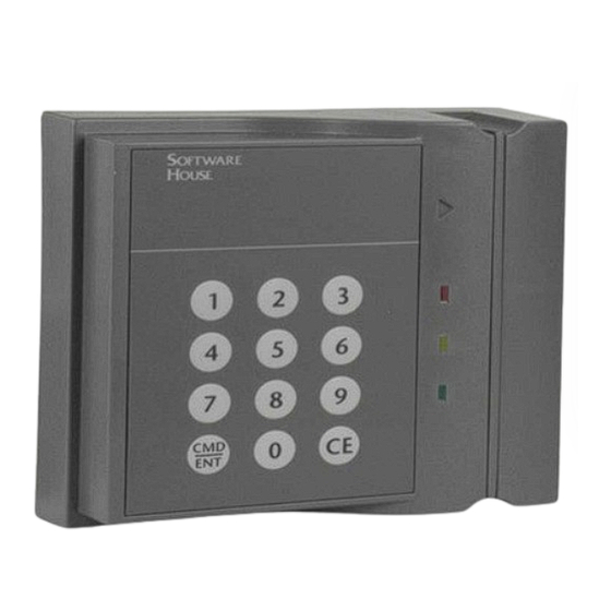
RM 1-4000, RM 2-4000, and RM 2L-4000 readers provide an enclosed RM-4 board
and attached multi-technology read head.
Figure 1 illustrates the RM xx-4000 Series Reader Models:
RM2-4000
RM1-4000
RM2L-4000
FIGURE 1. RM xx-4000 Series Reader Models
1
Advertisement
Table of Contents

Related Manuals for Software House RM 4000 Series


Summary of Contents for Software House RM 4000 Series
- Page 1 RM xx-4000 Series Readers Quick Start Installation Guide Version F1 Document Part Number UM-209 June 2012 OVERVIEW This guide provides quick start installation and connection information for RM xx-4000 Series Readers. Reader Models RM 1-4000, RM 2-4000, and RM 2L-4000 readers provide an enclosed RM-4 board and attached multi-technology read head.
- Page 2 125 KHz formats (HID and CASI ProxLite). The RM Multi-Technology reader includes a RoHS compliant RM-4 board in the RM housing and provides the same features and functionality as the Software House Multi- Technology Reader, including the ability to “flash” new card protocols or formats directly to the reader.
- Page 3 Overview Model RMxx-4000 TABLE 2. Proximity (125 KHz) Formats Supported Proximity (125 KHz) Formats Proximity (125 KHz) Formats As Shipped: Default Mode Supported Supported (On) HID® 26 Bit HID® Corporate 1000 HID® 36 Bit Wiegand HID® 37 Bit Wiegand Other HID® Pass-through Formats Deister Prox SmartFrame®...
- Page 4 Features FEATURES Universal compatibility with most 125 KHz Prox (including all HID® Prox formats), all ISO 15693, and ISO 14443A credentials (badges, disk tags and key fobs). Reads both 125 KHz and 13.56 MHz credentials in the same reader. Electrical protection (reverse polarity diode protection on power lines).
- Page 5 Features Controller Communication Wiegand Locally Flashable via RS485 Open Standards Compliance ISO 14443A ISO 14443B ISO 15693 Configure Using Program Card Pass-through - Default setting that allows the reader to send all data on the card. ...
-
Page 6: Specifications
Features Specifications The following specifications apply to all RM xx-4000 series readers: Data Cable: Recommended data cable is Belden #9841or equivalent. The maximum length is 4000 feet (1212 meters) between the controller and the RM xx-4000 reader. Power Wiring: Recommended power wiring is Belden #8461/8442 twisted pair. ... -
Page 7: Installation
4. Set the RM-4 (reader) address 5. Install the ARM-1 relay boards (optional) 6. Install the heater kit. (optional) 7. Mount the RM standard housing on the RM mount plate using the Software House security screwdriver (Part number 132-183). Install the RM Mount Figure 2 shows the RM standard housing, mount plate, and gasket. - Page 8 Installation Figure 3 shows the RM mount plate dimensions. 5.45" Wiring 4.11" access 3.66" 4.94" 2.47" 1.29" .83" 1.54" 8 mounting holes 1.82" .0.156" Thru, 0.280” Countersink 2.73" 3.64" 3.92" FIGURE 3. RM Mount Plate Dimensions This device has been approved for outdoor use when properly installed with RM Heater Kit Installation (P.N.
- Page 9 Installation Wire the RM xx-4000 Figure 4 shows RM xx-4000 Connections. Components FIGURE 4. RM xx-4000 Connection NOTE UL has not evaluated the ARM-1.
-
Page 10: Wiring The Inputs, Outputs, Reader Bus
RM xx-4000 Series Reader Setup Wiring the Inputs, Figure 5 shows RM-4 P1 and P5 wiring. Outputs, Reader Bus FIGURE 5. RM-4 Wiring Requirements NOTES 1. SW3-7 and SW3-8 refer to the Beeper on the RM-4. 2. P3 BEEP refers to the Beeper on the read head, if it exists. There is no Beeper on the RM xx-4000 read heads. - Page 11 RM xx-4000 Series Reader Setup RM xx-4000 Pre-wired Reader Connections The RM xx-4000 Reader is pre-wired, as shown in Figure 6. FIGURE 6. RM-4 xx-4000 Reader pre-Wired Connections NOTE The following P3 Reader pins are not used on the RM xx-4000 readers: RS-485 TXD/RXD + ...
- Page 12 RM xx-4000 Series Reader Setup Table 5 indicates the wiring for units with keypads. TABLE 5. Wiring for Units with Keypads J2 Pin Function Col 3 C3 C2 C1 Col 2 Col 1 Note: On a 3 x 4 Col 0 matrix keypad, Row 3 Pin 4 (C0) is not...
- Page 13 RM xx-4000 Series Reader Setup Grounding and Single RM Reader Shielding 1. When connecting a single RM reader to the reader bus, use twisted pair, shielded minimum 24 AWG cable. Attach the shield at the controller end. (Refer to TAB 2010-15 “RM Reader ESD Protection Guidelines.”) 2.
- Page 14 RM xx-4000 Series Reader Setup Figure 8 shows how to connect ARM-1 relay modules to the RM-4 outputs and how to wire NO (Normally Open) and NC (Normally Closed) supervised inputs. FIGURE 8. RM-4 Input/Output Connections NOTE Maximum distance from P5 to the ARM-1 is 25 feet. ...
-
Page 15: Installing The Heater
RM xx-4000 Series Reader Setup Installing the ARM-1 Two ARM-1 relay components can be connected to the RM xx-4000 series reader through the P5 connector (Table 6 ). Relay Module RM P5-1 is the common (+12 VDC) pin for either ARM-1. ... - Page 16 RM xx-4000 Series Reader Setup Figure 9 shows how to wire the RM heater kit. FIGURE 9. RM Heater Kit Wiring Figure 10 shows the location of the heater strips and thermostat on the RM mount plate. FIGURE 10. RM Installation Applying Heater Strips To apply heater strips: 1.
-
Page 17: Installing The Thermostat
RM xx-4000 Series Reader Setup 4. Gently roll the heater strip in place to remove air bubbles. 5. For maximum adhesion, do not apply pressure to the heater strips for 72 hours. NOTE Air gaps or bubbles under the heater cause localized overheating and possible heater burnout. - Page 18 Testing RM xx-4000 Readers TESTING RM XX-4000 To test RM xx-4000 series readers: READERS 1. Properly configure Readers, Inputs, and Outputs using the C•CURE Administration application and put the reader Online. 2. Measure the supply voltage to the RM-4. The voltage can be measured between pin 1 (+12 VDC supply) and pin 4 (ground) on the P4 connector.
-
Page 19: Configuration Notes
5. The reader is configured for the specified option(s) and is ready for use. Amber LED For more information about programming a card reader, refer to the PDF document entitled SWH Readers Program Card Use posted on the Software House Member Center. - Page 20 NOTES To upgrade the reader, you need to obtain the new firmware file from Software House, and then connect to the reader through a local RS485 connection, using terminals 9 and In most cases you can use a RS485-to-USB device, or a RS232-to-RS485 converter to connect the PC to the reader.
- Page 21 CAUTION: Equipment changes or modifications not expressly approved by Software House, the party responsible for FCC compliance, could void the user’s authority to operate the equipment, and could create a hazardous condition.
-
Page 22: Canadian Radio Emissions Requirements
Canadian Radio Emissions Requirements CANADIAN RADIO This digital apparatus does not exceed the Class A limits for radio noise emissions from digital apparatus set out in the Radio Interference Regulations of the Canadian EMISSIONS Department of Communications. REQUIREMENTS Le present appareil numerique n’emet pas de bruits radioelectriques depassant les limites applicables aux appareils numeriques de la class A prescrites dans le Reglement sur le brouillage radiolelectrique edicte par le ministere des Communications du Canada. -
Page 23: Important Safety Information
Important Safety Information Important Safety Information CAUTION: Changes to the RM4 xx-4000 not expressly approved by the party responsible for compliance could void your authority to operate the equipment. LIFE SAFETY REQUIREMENT: A fail-safe mechanism override must be installed at each card reader exit to allow people to leave the secure ... - Page 24 C•CURE and Software House are registered trademarks of Tyco International Ltd. and its respective companies. The trademarks, logos, and service marks displayed on this document are registered in the United States [or other countries]. Any misuse of the trademarks is strictly prohibited and Tyco International Ltd. will aggressively enforce its intellectual property rights to the fullest extent of the law, including pursuit of criminal prosecution wherever necessary.
Need help?
Do you have a question about the RM 4000 Series and is the answer not in the manual?
Questions and answers