Advertisement
Table of Contents
- 1 Controller Communications
- 2 Specification
- 3 Power Requirements
- 4 Installation
- 5 Wiring the Inputs, Outputs, Reader Bus
- 6 Setting up the Reader
- 7 Relay Module
- 8 Installing the Heater (Optional)
- 9 Installing the Thermostat
- 10 Testing Readers
- 11 Flash Upgrade
- 12 Important Safety Information
- Download this manual
RM2-4000-PI26 Reader
RM2L-4000-PI26 Reader
Installation Guide
Version A0
Document Part Number 8200- 1179-01
September 2015
OVERVIEW
This guide provides installation and connection information for RM2-4000-PI26 and
RM2L-4000-PI26 Readers.
NOTE
The RM2-4000-PI26 reader model is UL294 approved and not UL1076 approved.
The RM2L-4000-PI26 reader model is both UL294 and UL1076 approved.
Reader Models
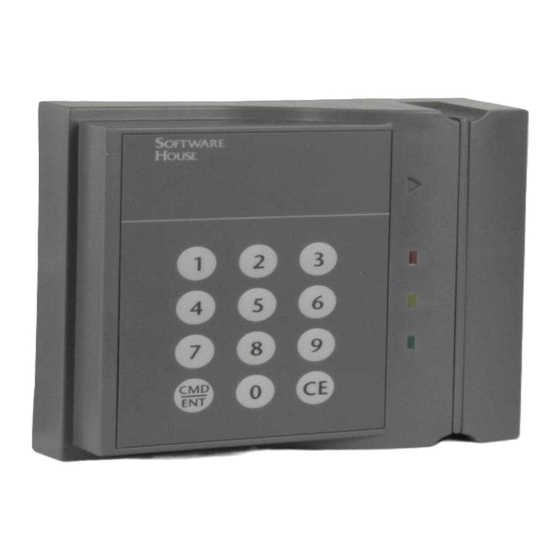
The RM readers provide an enclosed RM-4 board with multiple read heads. The readers
include two separate read heads in their enclosure – a multi-technology read head
positioned behind the right hand side of the reader, and a separate Indala prox read head
located behind the keypad portion of the reader. The multi-technology read head will
read both low frequency (125KHz) HID prox cards and high frequency (13.56 MHz)
smart cards.
FIGURE 1. Reader Models
RM2L-4000-PI26
RM2-4000-PI26
1
Advertisement
Table of Contents

Related Manuals for Software House RM2-4000-PI26


Summary of Contents for Software House RM2-4000-PI26
- Page 1 This guide provides installation and connection information for RM2-4000-PI26 and RM2L-4000-PI26 Readers. NOTE The RM2-4000-PI26 reader model is UL294 approved and not UL1076 approved. The RM2L-4000-PI26 reader model is both UL294 and UL1076 approved. Reader Models The RM readers provide an enclosed RM-4 board with multiple read heads. The readers include two separate read heads in their enclosure –...
- Page 2 TABLE 1. Part Numbers Reader Model Part Number With keypad; built-in RM-4 DS interface board RM2-4000-PI26 With keypad and LCD; built-in RM-4 DS interface board RM2L-4000-PI26 Supported The RM Multi-Technology reader can read three major card technologies – HID prox, Indala prox, and 13.56 MHz smart card.
- Page 3 Features Smart Card TABLE 3. Smart Card (13.56 MHz) Formats Supported (13.56 MHz) Formats Supported Smart Card (13.56 MHz) Formats Supported Enabled by Default? MiFARE® Sector MiFARE® Serial number, 32 Bit MiFARE® Serial number, 56 Bit MiFARE® Plus Serial number, 56 Bit MiFARE®...
-
Page 4: Controller Communications
Features Controller Communications Wiegand Locally Flashable via RS485 Open Standards Compliance ISO 14443A ISO 14443B ISO 15693 Configure Using Program Card Pass-through - Default setting that allows the reader to send all data on the card. ... -
Page 5: Specification
(UL603), power-limited power source with 4-hour standby capability. Connection to the ARM-1 has not been evaluated by UL. TABLE 4. Reader Power Supply Requirements Reader Power Requirements: 12 VDC RM2-4000-PI26 350 mA Max With Keypad Voltage Range: 12V RM2L-4000-PI26 350 mA Max... -
Page 6: Installation
Installation INSTALLATION To Install the Reader: 1. Install the reader mount plate. 2. Wire the components. 3. Connect and ground the cable shields on the reader bus. (Refer to TAB 2010-15 “RM Reader ESD Protection Guidelines.”) 4. Set the reader address. 5. - Page 7 Installation FIGURE 3. Mount Plate Dimensions 5.45" Wiring 4.11" access 3.66" 4.94" 2.47" 1.29" .83" 1.54" 8 mounting holes 1.82" .0.156" Thru, 0.280” Countersink 2.73" 3.64" 3.92" This device has been approved for outdoor use when properly installed with the RM Heater Kit Installation (P.N.
- Page 8 Installation Wiring the Reader Figure 4 shows reader connections. Components FIGURE 4. Reader Connection NOTE UL has not evaluated the ARM-1.
-
Page 9: Wiring The Inputs, Outputs, Reader Bus
Setting up the reader Wiring the Inputs, Figure 5 shows RM-4 P1 and P5 wiring. Outputs, Reader Bus FIGURE 5. RM-4 Wiring Requirements NOTES SW3-7 and SW3-8 refer to the Beeper on the RM-4. P3 BEEP refers to the Beeper on the read head, if it exists. There is no Beeper on the ... - Page 10 Setting up the reader Grounding and Single RM Reader Shielding When connecting a single RM reader to the reader bus, use twisted pair, shielded minimum 24 AWG cable. Attach the shield at the controller end. (Refer to TAB 2010-15 “RM Reader ESD Protection Guidelines.”) Attach a local earth ground (18 or 22 gauge) wire to the J5 component on the RM ...
-
Page 11: Relay Module
Setting up the reader Figure 7 shows how to connect ARM-1 relay modules to the reader outputs and how to wire NO (Normally Open) and NC (Normally Closed) supervised inputs. FIGURE 7. Reader Input/Output Connections Installing the ARM-1 Two ARM-1 relay components can be connected to the reader through the P5 connector (Table 5 ). -
Page 12: Installing The Heater (Optional)
Setting up the reader Installing the Heater The readers require a heater kit (Model C130-915) when installed outdoors in an environment where temperatures may drop below 40° F (5° C). (optional) The Model C130-915 heater kit contains the following parts: TABLE 6. -
Page 13: Installing The Thermostat
Setting up the reader FIGURE 9. RM Installation Applying Heater Strips To Apply Heater Strips: 1. Clean the attachment surface of the RM mount plate with a solvent such as alcohol (use all required precautions when handling solvents). 2. Carefully remove the release film from the adhesive. 3. -
Page 14: Testing Readers
CONFIGURATION The change to the default reader settings requires the use of special program cards that are available from the Software House Applications Department. Program cards are NOTES used to set a specific MIFARE read key and change other settings including card technologies to be read. -
Page 15: Flash Upgrade
5. The reader is configured for the specified option(s) and is ready for use. Amber LED Flash Upgrade For information about upgrading the firmware revision, refer to the PDF document entitled SWH Readers Download Firmware to Reader posted on the Software House Member Center. - Page 16 Compliance Compliance Specification Description Access Control System UL294 5 Edition Proprietary Alarm Units UL1076 5 Edition IEC60950-1 ITE – Safety International EN60950 ITE – Safety EN55022-:2010 ITE – Radio Disturbance Characteristics EN55024 ITE – Immunity Characteristics EN50130-4:2011 Alarm systems – Electromagnetic Compatibility IEC 62599-2 RoHS Restriction of hazardous substances...
-
Page 17: Important Safety Information
Revision: A0 Release Date: September 2015 This manual is proprietary information of Software House. Unauthorized reproduction of any portion of this manual is prohibited. The material in this manual is for information purposes only. It is subject to change without notice.
Need help?
Do you have a question about the RM2-4000-PI26 and is the answer not in the manual?
Questions and answers