
Related Manuals for RAYTAC MDBT42Q-AT2-UART-S


Summary of Contents for RAYTAC MDBT42Q-AT2-UART-S
- Page 1 Version: A Issued Date: 2022/10/26 User Guide (簡易使用手冊) 產品名稱 (Product) Demo Board for MDBT42Q-AT2 / PAT2 Peripheral / Slave role MDBT42Q – AT2 – UART – 產品型號 (Model No.) 韌體版本 (FW Rev.)
-
Page 2: Table Of Contents
Index Introduction ........................3 1.1. Contents of the Set ....................3 Hardware Description ....................4 Reference Circuit ......................6 AT Command ......................... 7 4.1. List of supported commands ................. 7 4.2. AT Command Sets ....................8 4.2.1. “Write” Commands ....................8 4.2.2. -
Page 3: Introduction
MDBT42Q-P192KV2. Please visit our website for spec sheet of every module mentioned above. 1.1. Contents of the Set Each set includes MDBT42Q-AT2-UART-S x 1 and mini-USB cable x 1. Please contact us if the set you receive is not complete. -
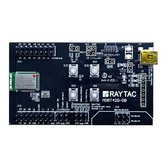
Page 4: Hardware Description
2. Hardware Description MDBT42Q-AT2 BLE module based on nRF52810. 32.768KHz crystal for external LF. 10uH & 15nH inductor for DC-to-DC mode. Interface to connect to external MCU. ADC input for battery detection only. Reference voltage is 0.6V. Example: ��1 formula: Input Voltage × = Reference Voltage ��1 +��2 →... - Page 5 Debug Interface, connecting to Nordic’s nRF5X DK. Important: Please be careful not to “erase” the module during testing. Raytac’s AT command firmware will not be shared. You may need to send the unit to us for re-programming when module’s FW is erased.
-
Page 6: Reference Circuit
3. Reference Circuit... -
Page 7: At Command
4. AT Command 4.1. List of supported commands Setting of device name Choose data rate of 1Mbps or 2Mbps on-air Set TX output power in 5 levels. Set advertising time Set connection interval under Mode 2 Enable/disable advertising Set LED pattern indicating advertising or connecting status 7 sets of UART baud rates Enable/disable UART flow control Enable/disable interface of UART hardware... -
Page 8: At Command Sets
4.2. AT Command Sets 4.2.1. “Write” Commands Command Description Set device name,Max. length of 20 characters AT+NAME e.g. AT+NAME123 (device name 123, 3 characters) AT+BAUDRATE9600 Set UART baud rate at 9600 bps,n,8,1 AT+BAUDRATE19200 Set UART baud rate at 19200 bps,n,8,1 AT+BAUDRATE38400 Set UART baud rate at 38400 bps,n,8,1 AT+BAUDRATE57600... - Page 9 Command Description Set advertising time (Hex) e.g. 0x001E (min. 30secs), (24) AT+ADVTIMEtttt 0x0E10 (Max. 3,600secs) 0x0000 (forever) (25) AT+DCDCDIS Disable DC to DC converter (26) AT+DCDCEN Enable DC to DC converter Set connection interval mode for iOS/Android APP usage (27) AT+CONNECTINTERVALMODE0 (min.
- Page 10 Direct-Action Command Description AT+RESET Set to reset system AT+ADVSTART Set to start advertising AT+ADVSTOP Set to stop advertising AT+SLEEP Set to get into deep sleep mode AT+DISCONNECT Terminate the connection AT+DEFAULT Back to default Set GPIO number p0.nn to high, AT+SETGPIOnnHIGH where “nn”...
-
Page 11: Read" Commands
4.2.2. “Read” Commands Direct-Action Command Description AT?NAME To retrieve device name AT?VERSION To retrieve firmware version AT?MACADDR To retrieve IC MAC address AT?BAUDRATE To retrieve current UART baud rate AT?FLOWCONTROL To retrieve UART status of flow control AT?TXPOWER To retrieve RF TX power AT?XTAL To retrieve status of oscillator AT?CONNECTINDICATOR... -
Page 12: Response (Default)
4.2.3. Response (Default) Command Response AT?NAME Raytac AT-UART (default) AT?VERSION e.g. version: 1.5 AT?MACADDR e.g. D352BDE1E414 0 baudrate9600 (default) AT?BAUDRATE (0 = 9600; 1 = 19200; 2 = 38400; 3 = 57600; 4 = 115200; 5 = 230400; 6 = 460800) - Page 13 Command Response 00c80708 (default: Hex, 0.2sec on / 1.8sec off, (15) AT?CONNECTPATTERN nnnn: 0x00c8, ffff: 0x0708) Display “ no data! ” string (default) (16) AT?SERIALNO (17) AT?ADCVALUE Value varies from input voltage 1 response en (default) (18) AT?RESPONSE (0 = disable response; 1 = enable response) (19) AT?ALLPARAMETERS Display value of all parameters, separated by "0x0d0x0a"...
-
Page 14: Default Info
4.3. Default Info Description Default Raytac AT-UART Device name 0x9E, 0xCA, 0xDC, 0x24, 0x0E, 0xE5, 0xA9, 0xE0 Base UUID 0x93, 0xF3, 0xA3, 0xB5, 0x00, 0x00, 0x40, 0x6E 0x0001 Service UUID TX characteristic: 0x0003; RX characteristic: 0x0002 Baud rate 9600bps,n,8,1 Status of flow control... -
Page 15: How To Control Via External Mcu
5. How to Control via External MCU 5.1. How to Send AT Commands ⚫ When BT is NOT connected, for ALL commands Output low to UART PD pin to enable UART interface. Please keep it LOW during the whole time when sending AT commands. Send any AT commands you want. - Page 16 ⚫ When BT is connected for following commands ONLY Write: AT+DISCONNECT, AT+SLEEP, AT+SETGPIOnnHIGH, AT+SETGPIOnnLOW, AT+SETGPIOnnOFF Read: AT?ADCVALUE Output low to UART PD pin to enable UART interface. Please keep it LOW during the whole time when sending AT commands. Output low to flash default pin to enable receiving AT commands when BT is connected.
-
Page 17: How To Transmit Data
5.2. How to Transmit Data * Only when BT is connected * Output low to UART PD pin to enable UART interface. Please keep it LOW during the whole time when transmitting data. Output high or NC to UART PD pin to turn off UART interface. -
Page 18: Test Report
6. Test Report All testing is done under PHY mode at 1M bps. 6.1. Current Test DC/DC Logic of UART PD pin Advertising Current Connected Current High 0.98 mA 0.51 mA Disable 1.78 mA 1.3 mA High 0.76 mA 0.54 mA Enable 1.1 mA 0.86 mA... -
Page 19: Throughput Test
6.2. Throughput Test Here D.L. means “Data Length” and D.I. means “Data Interval” in the table. ⚫ MCU → Peripheral (MDBT42Q-AT2/MDBT42Q-PAT2) → Central → Console Central Peripheral Baud Flow MCU D.L. MCU D.I. Total D.L. Total Data Rate Connection Interval Connection Interval Rate Control... - Page 20 ⚫ MCU → Central → Peripheral (MDBT42Q-AT2/MDBT42Q-PAT2) → Console Central Peripheral Baud Flow MCU D.L. MCU D.I. Total D.L. Total Data Rate Connection Interval Connection Interval Rate Control (bytes) (ms) (bytes) Trans. Time (sec) (k-bytes/sec) 262152 min = 20ms min = 20ms 9600 999432 1,042...
-
Page 21: Useful Links
7. Useful Links ⚫ Nordic Infocenter: https://infocenter.nordicsemi.com/index.jsp All the necessary technical files and software development kits of Nordic’s chip are on this website. ⚫ Nordic Developer Zone: https://devzone.nordicsemi.com/questions/ A highly recommended website for firmware developer. Interact with other developers and Nordic’s employees will help with your questions. The site also includes tutorials in detail to help you get started. -
Page 22: History Of Firmware Revision
History of Firmware Revision Compatible Release Description of Revision Note Ver. HW Build Date 2022/10/06 99-52810-02F 1st release. -
Page 23: Release Note
Release Note ⚫ 2022/10/26 Version A: 1 release...
Need help?
Do you have a question about the MDBT42Q-AT2-UART-S and is the answer not in the manual?
Questions and answers