
Related Manuals for RAYTAC MDBT50Q-DB-ATMS


Summary of Contents for RAYTAC MDBT50Q-DB-ATMS
- Page 1 Version: A Issued Date: 2020/05/30 User Guide (簡易使用手冊) 產品名稱 (Product): Demo Board for MDBT50Q-ATMS / MDBT50Q-PATMS MDBT50Q – DB – ATMS 產品型號 (Model No.): 韌體版本 (FW Revision): 1.0 DEFAULT ROLE IS “PERIPHERAL / SLAVE”...
-
Page 2: Table Of Contents
Index Introduction ........................3 1.1. Contents of the Set ....................3 Hardware Description ....................4 Reference Circuit ......................6 AT Command ......................... 7 4.1. List of supported commands ................. 7 4.1.1. Central ........................7 4.1.2. Peripheral ......................8 4.2. AT Command Sets ....................9 4.2.1. -
Page 3: Introduction
1. Introduction This document shows how to use the demo board (MDBT50Q-DB-ATMS) to test function of MDBT50Q-ATMS & MDBT50Q-PATMS. MDBT50Q-DB-ATMS is designed for testing and debugging without building your own board. The board is only available with MDBT50Q-ATMS (chip antenna) module. MDBT50Q-ATMS will be pre-programmed with Raytac’s AT command firmware. -
Page 4: Hardware Description
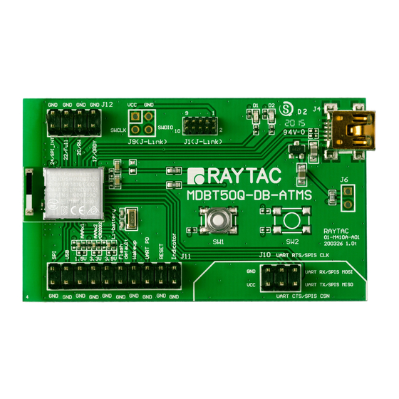
2. Hardware Description MDBT50Q-ATMS BLE module based on nRF52833. 32.768KHz crystal for external LF oscillator . External MCU control Interface ADC input for battery detection only. Reference voltage is 0.6V. Example: ��1 formula: Input Voltage × = Reference Voltage ��1 +��2 →... - Page 5 Wake-up(Scan) key. 3.3V LDO to power up MDBT50Q-ATMS. LED for status indicator USB interface for USB Mode (10) Select USB Mode...
-
Page 6: Reference Circuit
3. Reference Circuit... -
Page 7: At Command
4. AT Command 4.1. List of supported commands 4.1.1. Central Hardware selecting of UART or USB interface Enable/disable interface of UART hardware for saving power Setting of device role as Central or Peripheral Setting of scanned device name Setting of scanned base UUID / service UUID / TX character / RX character Setting of scanned RSSI threshold Select data rate of 1 Mbps, 2 Mbps or 125 Kbps on-air Select output power in 6 levels. -
Page 8: Peripheral
4.1.2. Peripheral Hardware selecting of UART or USB interface Enable/disable interface of UART hardware for saving power Setting of device role as Central or Peripheral Setting of advertising device name Setting of base UUID / service UUID / TX character / RX character Select data rate of 1 Mbps, 2 Mbps or 125 Kbps on-air Select output power in 6 levels. -
Page 9: At Command Sets
4.2. AT Command Sets 4.2.1. “Central” Commands ⚫ Central “Write” Command Description AT+CENTRAL Set device role as Central AT+PERIPHERAL Set device role as Peripheral Set device name, Max. length of 20 characters AT+NAME e.g. AT+NAME123 (device name 123, 3 characters) Set base UUID for NUS (Hex), AT+BASEUUID e.g. - Page 10 Command Description Set connection interval mode for Peripheral 20ms/40ms (18) AT+CONNECTINTERVALMODE0 usage (min. 20ms / Max. 40ms), Set connection interval mode for Peripheral 8ms/8ms (19) AT+CONNECTINTERVALMODE1 usage (min. 8ms / Max. 8ms) Set connection interval mode for Peripheral usage (20) AT+CONNECTINTERVALMODE2 (programmable: min.
- Page 11 Command Description Set idle time (Hex) e.g. 0x001E (min. 30secs), (37) AT+IDLETIMEtttt 0x0258 (Max. 600secs) 0x0000 (forever) (38) AT+SCANOLDSTART Set to start scanning paired device (39) AT+SCANNEWSTART Set to start scanning ALL devices (40) AT+SCANSTOP Set to stop scanning (41) AT+DISCONNECT Terminate the connection Set LED idle pattern (Hex), where...
- Page 12 Back to default Set to output the list of all devices which meet the setting of base UUID. Output information in sequence includes: (1) RSSI (2) MAC address (3) device name e.g. -40, AABBCCDDEEFF, Raytac AT-UART (ASCII) stands for (57) AT+SCANLIST...
- Page 13 (62) AT+BEACONINFODIS Disable scanning beacon data Switch to command mode when BLE is connected (63) AT+COMMANDEN (USB communication mode only) Switch to transmission mode when BLE is connected (64) AT+COMMANDDIS (USB communication mode only) (65) AT+BOOTLOADER For Raytac Test only...
-
Page 14: Central "Read
⚫ Central “Read” Command Description AT?ROLE To retrieve device role AT?NAME To retrieve scanned device name AT?BASEUUID To retrieve base UUID value (Hex) AT?SERVICEUUID To retrieve service UUID value (Hex) AT?TXCHARACTERUUID To retrieve TX character UUID value (Hex) AT?RXCHARACTERUUID To retrieve RX character UUID value (Hex) AT?RSSITHRESHOLD To retrieve scanning new RSSI threshold value (Ascii) AT?CONNECTRSSI... - Page 15 Command Description (29) AT?RESPONSE To retrieve status of response (30) AT?VERSION To retrieve firmware version (31) AT?COMPANYID To retrieve company ID value (Hex) (32) AT?BEACONUUID To retrieve beacon UUID value (Hex) (33) AT?BEACONINFO To retrieve beacon information (34) AT?ALLPARAMETERS To retrieve value of all parameters...
-
Page 16: Peripheral" Commands
4.2.2. “Peripheral” Commands ⚫ Peripheral “Write” Command Description AT+CENTRAL Set device role to central AT+PERIPHERAL Set device role to peripheral Set device name. Max. length of 20 characters AT+NAME e.g. AT+NAME123 (device name 123, 3 characters) Set base UUID for NUS (Hex), AT+BASEUUID e.g. - Page 17 Command Description Set connection interval mode for Peripheral 20ms/40ms (17) AT+CONNECTINTERVALMODE0 usage (min. 20ms / Max. 40ms), Set connection interval mode for Peripheral 8ms/8ms (18) AT+CONNECTINTERVALMODE1 usage (min. 8ms / Max. 8ms) Set connection interval mode for Peripheral usage (19) AT+CONNECTINTERVALMODE2 (programmable: min.
- Page 18 (52) AT+DEFAULT Back to default setting Switch to command mode when BLE is connected (53) AT+COMMANDEN (USB communication mode only) Switch to transmission mode when BLE is connected (54) AT+COMMANDDIS (USB communication mode only) (55) AT+BOOTLOADER For Raytac Test only...
-
Page 19: Peripheral "Read
⚫ Peripheral “Read” Command Description AT?ROLE To retrieve device role AT?NAME To retrieve scanned device name AT?BASEUUID To retrieve base UUID value (Hex) AT?SERVICEUUID To retrieve service UUID value (Hex) AT?TXCHARACTERUUID To retrieve TX character UUID value (Hex) AT?RXCHARACTERUUID To retrieve RX character UUID value (Hex) AT?PHYMODE To retrieve status of PHY mode AT?TXPOWER... -
Page 20: Response (Default)
4.2.3. Response (Default) ⚫ Central Command Response AT?ROLE central AT?NAME MDBT50Q-ATMS (default) 9ECADC240EE5A9E093F3A3B50000406E AT?BASEUUID (default: Hex, uuuuuuuuuuuuuuuuuuuuuuuuuuuuuuuu: 0x9ECADC240EE5A9E093F3A3B50000406E) AT?SERVICEUUID 0001 (default: Hex, uuuu: 0x0001) AT?TXCHARACTERUUID 0003 (default: Hex, uuuu: 0x0003) AT?RXCHARACTERUUID 0002 (default: Hex, uuuu: 0x0002) AT?RSSITHRESHOLD -51 (default: Ascii, nnn: -51) AT?CONNECTRSSI -30 (dBm, value varies from RSSI) 0 PHY mode 1Mbps (default) - Page 21 Command Response 0000 (default: Hex, forever advertising with no timeout, (16) AT?IDLETIME tttt: 0x0000) 0000 (default: Hex, forever scanning paired device (17) AT?SCANOLDTIME with no timeout, tttt: 0x0000) 0000 default: Hex, forever scanning ALL devices with no (18) AT?SCANNEWTIME timeout, tttt: 0x0000) 00640f3c (default: Hex, 0.1sec on / 3.9sec off, (19) AT?IDLEPATTERN...
- Page 22 Command Response 0112233445566778899AABBCCDDEEFF0 (default: Hex, uuuuuuuuuuuuuuuuuuuuuuuuuuuuuuuu: (32) AT?BEACONUUID 0x0112233445566778899AABBCCDDEEFF0) 0 beaconinfo dis (default) (0 = disable to print beacon info.; (33) AT?BEACONINFO 1 = enable to print beacon info.) Display value of all parameters, separated by “0x0d0x0a” (34) AT?ALLPARAMETERS...
-
Page 23: Peripheral
⚫ Peripheral Command Response AT?ROLE peripheral AT?NAME MDBT50Q-ATMS (default) 9ECADC240EE5A9E093F3A3B50000406E AT?BASEUUID (default: Hex, uuuuuuuuuuuuuuuuuuuuuuuuuuuuuuuu: 0x9ECADC240EE5A9E093F3A3B50000406E) AT?SERVICEUUID 0001 (default: Hex, uuuu: 0x0001) AT?TXCHARACTERUUID 0003 (default: Hex, uuuu: 0x0003) AT?RXCHARACTERUUID 0002 (default: Hex, uuuu: 0x0002) 0 PHY mode 1Mbps (default) AT?PHYMODE (0 = 1Mbps; 1 = 2Mbps; 2 = 125Kbps) 5 txpower 8dbm (default) AT?TXPOWER (0 = 4dBm;... - Page 24 Command Response 0000 (default: Hex, forever advertising with no timeout, (14) AT?ADVTIME tttt: 0x0000) (15) AT?ADVINTERVALTIME 0040 (default:Hex, 40 ms) 01F1001F4 (default: Hex, 0.5sec on / 0.5sec off, (16) AT?ADVPATTERN nnnn: 0x01F4, fff: 0x01F4) 00c80708 (default: Hex, 0.2sec on / 1.8sec off, (17) AT?CONNECTPATTERN nnnn: 0x00c8, ffff: 0x0708)
-
Page 25: Default Info
4.3. Default Info 4.3.1. Central Description Default Scanned device name MDBT50Q-ATMS 0x9E, 0xCA, 0xDC, 0x24, 0x0E, 0xE5, 0xA9, 0xE0, Base UUID 0x93, 0xF3, 0xA3, 0xB5, 0x00, 0x00, 0x40, 0x6E 0x0001 Service UUID TX characteristic: 0x0003; RX characteristic: 0x0002 Scanning new RSSI threshold -51 (Ascii). - Page 26 Description Default (23) State of response Enabled (24) Firmware version (25) Company ID 0x004C 0x01, 0x12, 0x23, 0x34, 0x45, 0x56, 0x67, 0x78, (26) Beacon UUID 0x89, 0x9A, 0xAB, 0xBC, 0xCD, 0xDE, 0xEF, 0xF0 (27) Communication Interface By hardware setting...
-
Page 27: Peripheral
4.3.2. Peripheral Description Default Device name MDBT50Q-ATMS 0x9E, 0xCA, 0xDC, 0x24, 0x0E, 0xE5, 0xA9, 0xE0, Base UUID 0x93, 0xF3, 0xA3, 0xB5, 0x00, 0x00, 0x40, 0x6E 0x0001 Service UUID TX characteristic: 0x0003; RX characteristic: 0x0002 PHY mode 1Mbps RF TX power +8dBm Connection interval mode Mode 0(min. -
Page 28: How To Control External Mcu
5. How to Control External MCU 5.1. How to Send AT Commands 5.1.1. UART Mode ⚫ When BT is connected, for ALL commands Output low to UART PD pin to enable UART interface. Please keep it enabling during the whole time when sending AT commands. Send any AT commands you want. -
Page 29: Usb Mode
5.1.2. USB Mode ⚫ When BT is connected, for ALL commands Send any AT commands you want through COM port software. Please wait for at least 250 ms between sending each command. Send command “ AT+RESET ” (not HW reset) to save all your settings through COM port software. -
Page 30: How To Return To Flashed Default Setting
5.2. How to Return to Flashed Default Setting * Only when BT is NOT connected * * Note that default baud rate is “9600bps,n,8,1”. For other default, please check “4.3 Default Info” ⚫ Use Hardware Method Read indicator pin first to check if BT is NOT in connection. Output a low pulse to flash default pin, then system will return to default setting. -
Page 31: Default Definition Of Connect/Adv Led Status
5.3. Default Definition of Connect/ADV LED Status ⚫ Central Mode LED Status Idle Breathing light Connected 0.2 sec ON / 1.8 secs OFF Scan the paired device 1 sec ON / 1 sec OFF Scan all devices 0.1 sec ON / 0.1 sec OFF ⚫... -
Page 32: How To Start Scanning
5.4. How to Start Scanning This section describes how to start scanning using a physical button (hardware) or the AT Command (firmware) under various occasions. Before getting started, here are some notes applied to both methods. ⚫ Each central device is only able to pair with 1 Peripheral. ⚫... - Page 33 ⚫ Use Key/Button START Scanning Paired Device --- Press the button for less than 2 seconds and release it to start scanning paired device. START Scanning All Devices --- Press the button for 2 seconds or longer directly to start scanning all devices. STOP Scanning Paired / All Device(s) Press the button for less than 2 seconds and release it to stop scanning.
- Page 34 ⚫ Use AT Command START Scanning Paired Device --- Enter “AT+SCANOLDSTART” to start scanning paired device. START Scanning All Devices --- Enter “AT+SCANNEWSTART” to start scanning all devices. STOP Scanning Paired / All Device(s) Enter “AT+SCANSTOP” to stop scanning. The device will be back to idle and go into deep sleep after a given timeout.
-
Page 35: Throughput Test
5.5. Throughput Test means “Data Length” and means “Data Interval” in the table. Here D.L. D.I. ⚫ MCU→ Peripheral (MDBT50Q-ATMS UART)→ Central (MDBT50Q-ATMS UART)→ PC Console Under PHY mode 2 Mbps Central Peripheral Baud Flow MCU D.L. MCU D.I. Total D.L. Total Data Rate Connection Interval... - Page 36 Under PHY mode 1 Mbps Central Peripheral Baud Flow MCU D.L. MCU D.I. Total D.L. Total Data Rate Connection Interval Connection Interval Rate Control (bytes) (ms) (bytes) Trans. Time (sec) (k-bytes/sec) min = 20 ms min = 20 ms 9600 1049200 1095 0.93...
- Page 37 Under PHY mode 125 Kbps Central Peripheral Baud Flow MCU D.L. MCU D.I. Total D.L. Total Data Rate Connection Interval Connection Interval Rate Control (bytes) (ms) (bytes) Trans. Time (sec) (k-bytes/sec) min = 20 ms min = 20 ms 9600 1049200 1095 0.93...
- Page 38 ⚫ MCU→ Central (MDBT50Q-ATMS UART)→ Peripheral (MDBT50Q-ATMS UART)→ PC Console Under PHY mode 2 Mbps Central Peripheral Baud Flow MCU D.L. MCU D.I. Total D.L. Total Data Rate Connection Interval Connection Interval Rate Control (bytes) (ms) (bytes) Trans. Time (sec) (k-bytes/sec) min = 20 ms min = 20 ms...
- Page 39 Under PHY mode 1 Mbps Central Peripheral Baud Flow MCU D.L. MCU D.I. Total D.L. Total Data Rate Connection Interval Connection Interval Rate Control (bytes) (ms) (bytes) Trans. Time (sec) (k-bytes/sec) min = 20 ms min = 20 ms 9600 1049200 1095 0.93...
- Page 40 Under PHY mode 125 Kbps Central Peripheral Baud Flow MCU D.L. MCU D.I. Total D.L. Total Data Rate Connection Interval Connection Interval Rate Control (bytes) (ms) (bytes) Trans. Time (sec) (k-bytes/sec) min = 20 ms min = 20 ms 9600 1049200 1095 0.93...
- Page 41 ⚫ MCU→ Peripheral (MDBT50Q-ATMS UART)→ Central (MDBT50Q-RX-ATM)→ PC Console Under PHY mode 2 Mbps Central Peripheral Baud Flow MCU D.L. MCU D.I. Total D.L. Total Data Rate Connection Interval Connection Interval Rate Control (bytes) (ms) (bytes) Trans. Time (sec) (k-bytes/sec) min = 20 ms min = 20 ms 9600...
- Page 42 Under PHY mode 1 Mbps Central Peripheral Baud Flow MCU D.L. MCU D.I. Total D.L. Total Data Rate Connection Interval Connection Interval Rate Control (bytes) (ms) (bytes) Trans. Time (sec) (k-bytes/sec) min = 20 ms min = 20 ms 9600 1049200 1095 0.93...
- Page 43 Under PHY mode 125 Kbps Central Peripheral Baud Flow MCU D.L. MCU D.I. Total D.L. Total Data Rate Connection Interval Connection Interval Rate Control (bytes) (ms) (bytes) Trans. Time (sec) (k-bytes/sec) min = 20 ms min = 20 ms 9600 1049200 1095 0.93...
- Page 44 ⚫ MCU→ Peripheral (MDBT50Q-ATMS UART)→ Central (MDBT42Q-ATM/PATM)→ PC Console Under PHY mode 2 Mbps Central Peripheral Baud Flow MCU D.L. MCU D.I. Total D.L. Total Data Rate Connection Interval Connection Interval Rate Control (bytes) (ms) (bytes) Trans. Time (sec) (k-bytes/sec) min = 20 ms min = 20 ms 9600...
- Page 45 Under PHY mode 1 Mbps Central Peripheral Baud Flow MCU D.L. MCU D.I. Total D.L. Total Data Rate Connection Interval Connection Interval Rate Control (bytes) (ms) (bytes) Trans. Time (sec) (k-bytes/sec) min = 20 ms min = 20 ms 9600 1049200 1095 0.93...
-
Page 46: Useful Links
Useful Links ⚫ Nordic Infocenter: https://infocenter.nordicsemi.com/index.jsp All the necessary technical files and software development kits of Nordic’s chip are on this website. ⚫ Nordic Developer Zone: https://devzone.nordicsemi.com/questions/ A highly recommended website for firmware developer. Interact with other developers and Nordic’s employees will help with your questions. The site also includes tutorials in detail to help you get started. -
Page 47: History Of Firmware Revision
History of Firmware Revision Compatible Release Description of Revision Note Ver. HW Build Date 2020/05/30 release. 99-52833-03A... -
Page 48: Release Note
Release Note ⚫ 2020/05/30 Version A: 1 release...
Need help?
Do you have a question about the MDBT50Q-DB-ATMS and is the answer not in the manual?
Questions and answers