
Related Manuals for RAYTAC MDBT42Q-AT-UART-M


Summary of Contents for RAYTAC MDBT42Q-AT-UART-M
- Page 1 Version: C Issued Date: 2020/04/22 User Guide (簡易使用手冊) 產品名稱 (Product): Demo Board for MDBT42Q-ATM / PATM MDBT42Q – AT – UART – 產品型號 (Model No.): 韌體版本 (FW Revision): 1.2...
-
Page 2: Table Of Contents
Index Introduction ........................3 1.1. Contents of the Set ....................3 Hardware Description ....................4 Reference Circuit ......................6 Connecting for the First Time ..................7 AT Command ......................... 8 5.1. List of supported commands ................. 8 5.2. AT Command Sets ....................9 5.3. -
Page 3: Introduction
MDBT42Q-512KV2 and MDBT42Q-P512KV2. Please visit our website for spec sheet of every module mentioned above. 1.1. Contents of the Set Each set includes MDBT42Q-AT-UART-M x 1 and mini-USB cable x 1. Please contact us if the set you receive is not complete. -
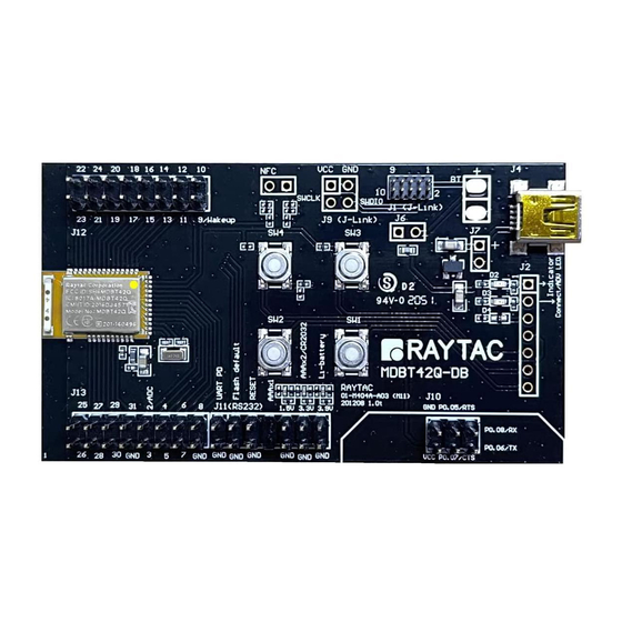
Page 4: Hardware Description
2. Hardware Description MDBT42Q-ATM BLE module based on nRF52832. 32.768KHz crystal for external LF. 10uH & 15nH inductor for DC-to-DC mode. Interface to connect to external MCU. ADC input for battery detection only. Reference voltage is 0.6V. Example: ��1 formula: Input Voltage × = Reference Voltage ��1 +��2 →... - Page 5 Debug interface, connecting to Nordic’s nRF5X DK. Important: Please be careful not to “erase” the module during testing. Raytac’s AT command firmware will not be shared. You may need to send the unit to us for re-programming when module’s FW is erased.
-
Page 6: Reference Circuit
3. Reference Circuit... -
Page 7: Connecting For The First Time
4. Connecting for the First Time Please follow instruction below to connect MDBT42Q-AT-UART-S to MDBT42Q-AT-UART-M. 1. Make sure the distance between 2 boards is less than 30 cm. 2. Press the “pairing key” on MDBT42Q-AT-UART-M for over 2 seconds. 3. When seeing LED blinks like below, the connection is successful. -
Page 8: At Command
5. AT Command 5.1. List of supported commands Setting of scanned device name Setting of scanned base UUID/service UUID/TX character/RX character Setting of scanned RSSI threshold Choose data rate of 1M bps or 2M bps on-air Set TX output power in 5 levels. Set scanning time Enable/disable scanning Set LED pattern indicating scanning or connecting status... -
Page 9: At Command Sets
5.2. AT Command Sets 5.2.1. “Write” Commands Command Description Set scanned device name. Max. length of 20 characters AT+NAME e.g. AT+NAME123 (device name 123, 3 characters) AT+RESET Set to reset system AT+SCANOLDSTART Set to start scanning paired device AT+SCANNEWSTART Set to start scanning ALL devices AT+SCANSTOP Set to stop scanning AT+SLEEP... - Page 10 Command Description (25) AT+PHYMODE1MBPS Set PHY mode at 1Mbps (26) AT+PHYMODE2MBPS Set PHY mode at 2Mbps (27) AT+WAKEUPLOW Set logic low at wake-up when in deep sleep (28) AT+WAKEUPHIGH Set logic high at wake-up when in deep sleep Set idle time (Hex) e.g.
- Page 11 Command Description Set LED connecting pattern (Hex), where n = time when LED on, f = time when LED off e.g. 0x0064 (min. 100ms) (37) AT+CONNECTPATTERNnnnnffff 0x1388 (Max. 5,000ms) 0x00000000 (off) 0xFFFFFFFF (on) Set LED pattern for scanning paired device (Hex), where n = time when LED on, f = time when LED off e.g.
- Page 12 Command Description AT+BEACONUUID Set UUID for beacon (Hex), (48) uuuuuuuuuuuuuuuu e.g. 0112233445566778899AABBCCDDEEFF0 uuuuuuuuuuuuuuuu Set TX character UUID for NUS (Hex), (49) AT+TXCHARACTERUUIDuuuu e.g. 0x0003 Set RX character UUID for NUS (Hex), (50) AT+RXCHARACTERUUIDuuuu e.g. 0x0002 Set service UUID for NUS (Hex), (51) AT+SERVICEUUIDuuuu e.g.
- Page 13 5.2.2. “Read” Commands Command Description AT?NAME To retrieve scanned device name AT?VERSION To retrieve firmware version AT?MACADDR To retrieve IC MAC address AT?BAUDRATE To retrieve current UART baud rate AT?FLOWCONTROL To retrieve UART status of flow control AT?TXPOWER To retrieve RF TX power AT?XTAL To retrieve status of 32.768KHz oscillator AT?CONNECTINDICATOR...
- Page 14 Command Description (28) AT?TXCHARACTERUUID To retrieve TX character UUID value (Hex) (29) AT?RXCHARACTERUUID To retrieve RX character UUID value (Hex) (30) AT?SERVICEUUID To retrieve service UUID value (Hex) (31) AT?BASEUUID To retrieve base UUID value (Hex) (32) AT?ALLPARAMETERS To retrieve value of all parameters...
- Page 15 5.2.3. Response (Default) Command Response AT?NAME Raytac AT-UART (default) AT?VERSION e.g. version: 1.0 AT?MACADDR e.g. D352BDE1E414 0 baudrate9600 (default) AT?BAUDRATE (0 = 9600; 1 = 19200; 2 = 38400; 3 = 57600; 4 = 115200; 5 = 230400; 6 = 460800)
- Page 16 Command Response 0 connect interval mode 0 (default) (15) AT?CONNECTINTERVALMODE (0 = connection interval for Peripheral 20ms/40ms usage 1 = connection interval for Peripheral 8ms/8ms usage) 00640f3c (default: Hex, 0.1sec on / 3.9sec off, (16) AT?IDLEPATTERN nnnn: 0x0064, ffff: 0x0f3c) 00c80708 (default: Hex, 0.2sec on / 1.8sec off, (17) AT?CONNECTPATTERN...
-
Page 17: Default Info
5.3. Default Info Description Default Scanned device name Raytac AT-UART 0x9E, 0xCA, 0xDC, 0x24, 0x0E, 0xE5, 0xA9, 0xE0, Base UUID 0x93, 0xF3, 0xA3, 0xB5, 0x00, 0x00, 0x40, 0x6E 0x0001 Service UUID TX characteristic: 0x0003; RX characteristic: 0x0002 Baud rate 9600bps,n,8,1... - Page 18 Description Default (23) Scanning new RSSI threshold -51 (Ascii). 0x01, 0x12, 0x23, 0x34, 0x45, 0x56, 0x67, 0x78, (24) Beacon UUID 0x89, 0x9A, 0xAB, 0xBC, 0xCD, 0xDE, 0xEF, 0xF0 (25) Company ID 0x004C...
-
Page 19: How To Control External Mcu
6. How to Control External MCU 6.1. How to Send AT Commands ⚫ When BT is NOT connected (for all commands) Output low to P0.10 (UART PD pin) to enable UART interface. Please keep it enabling during the whole time when sending AT commands. Send any AT commands you want. -
Page 20: How To Return To Flashed Default Setting
6.2. How to Return to Flashed Default Setting * Only when BT is NOT connected * * Note that default baud rate is “9600bps,n,8,1”. For other default, please check “ 5.3 Default Info” ⚫ Use Hardware Method Read P0.03 (indicator pin) first to check if BT is NOT in connection. Output a low pulse to P0.11 (flash default pin), then system will return to default setting. - Page 21 ⚫ Default Definition of LED (P0.4) Status Mode LED Status Idle 0.1 sec ON / 3.9 secs OFF Connected 0.2 sec ON / 1.8 secs OFF Scan the paired device 1 sec ON / 1 sec OFF Scan all devices 0.1 sec ON / 0.1 sec OFF...
-
Page 22: How To Start Scanning
6.3. How to Start Scanning This section describes how to start scanning using a physical button (hardware) or the AT Command (firmware) under various occasions. Before getting started, here are some notes applied to both methods. ⚫ Each central device is only able to pair with 1 Peripheral. ⚫... - Page 23 ⚫ Use Key/Button START Scanning Paired Device --- Press the button for less than 2 seconds and release it to start scanning paired device. START Scanning All Devices --- Press the button for 2 seconds or longer directly to start scanning all devices. STOP Scanning Paired / All Device(s) Press the button for less than 2 seconds and release it to stop scanning.
- Page 24 ⚫ Use AT Command START Scanning Paired Device --- Enter “AT+SCANOLDSTART” to start scanning paired device. START Scanning All Devices --- Enter “AT+SCANNEWSTART” to start scanning all devices. STOP Scanning Paired / All Device(s) Enter “AT+SCANSTOP” to stop scanning. The device will be back to idle and go into deep sleep after a given timeout.
-
Page 25: Report Of Data Transmission
7. Report of Data Transmission “Data Length” and means “Data Interval” in the table. All testing is done under PHY mode at 1M bps D.L. means D.I. 7.1. MCU → Peripheral (MDBT42Q-AT/MDBT42Q-PAT) → Central → Console Central Peripheral Baud Flow MCU D.L. - Page 26 7.2. MCU → Central → Peripheral (MDBT42Q-AT/MDBT42Q-PAT) → Console Central Peripheral Baud Flow MCU D.L. MCU D.I. Total D.L. Total Data Rate Connection Interval Connection Interval Rate Control (bytes) (ms) (bytes) Trans. Time (sec) (k-bytes/sec) 262152 min = 20ms min = 20ms 9600 999432 1,042...
-
Page 27: Useful Links
Useful Links ⚫ Nordic Infocenter: https://infocenter.nordicsemi.com/index.jsp All the necessary technical files and software development kits of Nordic’s chip are on this website. ⚫ Nordic DevZone: https://devzone.nordicsemi.com/questions/ A highly recommended website for firmware developer. Interact with other developers and Nordic’s employees will help with your questions. The site also includes tutorials in detail to help you get started. -
Page 28: History Of Firmware Revision
History of Firmware Revision Compatible Release Description of Revision Note Ver. HW Build Date 2018/10/15 release. 99-52832-12A 2019/05/17 Fixed bug of not sending PHY information to peripheral device after BLE connection. 99-52832-12B 2020/04/13 Fixed issues of reading MAC address. 99-52832-12C... -
Page 29: Release Note
Release Note ⚫ 2018/10/30 Version A: 1 release ⚫ 2019/09/23 Version B: (1) Corrected the illustration and note from “wake-up key” to “pairing key” in Chapter 2: Hardware Description. (2) Added how to connect the demo board for the 1 time in Chapter 4: Connecting for the 1 Time.
Need help?
Do you have a question about the MDBT42Q-AT-UART-M and is the answer not in the manual?
Questions and answers