Table of Contents
Advertisement
Quick Links
INSTALLATION AND OPERATING
INSTRUCTIONS
Heat Pump
Pool & Spa
Heater
Professional Series
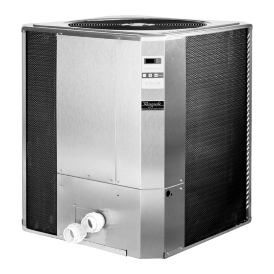
PS10353ti-E-HC
PS10354ti-E-HC
PS10355ti-E-HC
FOR YOUR SAFETY: Do not store or use gasoline or other flammable vapors and
liquids or other combustible materials in the vicinity of this or any other appliance.
To do so may result in an explosion or fire.
NOTE: The instructions in this manual are for the use of qualified individuals specially trained and experienced
in the installation and maintenance of this type of equipment and related system components. Installation and
service personnel are required by some states to be licensed. Persons not qualified shall not attempt to install,
service, or maintain this equipment.
This manual should be maintained in legible condition and kept adjacent to the heater or in a safe place for future
use.
Effective: 04-01-22
Replaces: 12-15-14
P/N 241460 Rev. 4
Advertisement
Table of Contents

Related Manuals for Rheem Raypak Professional Series


Summary of Contents for Rheem Raypak Professional Series
- Page 1 INSTALLATION AND OPERATING INSTRUCTIONS Heat Pump Pool & Spa Heater Professional Series PS10353ti-E-HC PS10354ti-E-HC PS10355ti-E-HC FOR YOUR SAFETY: Do not store or use gasoline or other flammable vapors and liquids or other combustible materials in the vicinity of this or any other appliance. To do so may result in an explosion or fire.
- Page 2 Revision 4 reflects the following changes: Reformatted to InDesign from Quark. Additional Metric and Celsius data added as needed to text, figures, and tables. Text clarity improved throughout using improved word choice to avoid ambiguity or incompleteness. Introduction revised on page 5. Figures 5 revised on page 13.
-
Page 3: Table Of Contents
TABLE OF CONTENTS 1. WARNINGS ............4 15. MAINTENANCE ............ 10 Pay Attention to these Terms ........4 Air Coil Cleaning ........... 10 Cabinet Care (optional) ......... 11 2. WATER CHEMISTRY ..........5 Unplug Condensation Drain Holes ......11 3. INTRODUCTION ............. 5 16. -
Page 4: Warnings
1. WARNINGS Pay Attention to these Terms Indicates the presence of immediate hazards which will cause severe personal injury, death or substantial DANGER property damage if ignored. ndicates the presence of hazards or unsafe practices which could cause severe personal injury, death or WARNING substantial property damage if ignored. -
Page 5: Water Chemistry
• Automatic chemical dosing devices salt 2. WATER CHEMISTRY chlorinators are usually more efficient in heated (Corrosive water voids all warranties) water. Unless controlled, they can lead to excessive chlorine level which can damage your heater. For your health and the protection of your pool equipment, it is essential that your water be chemically balanced. - Page 6 • Irrigation water should be directed away from the WARNING: This unit is designed for outdoor heater-water spray can damage the heat pump pool installation. It is NOT certified for indoor installation. heater. DO NOT install it in an enclosed area such as a shed or garage, or under a porch or deck.
- Page 7 Figure 2. High Wind Installation Requirements...
-
Page 8: Electrical Connections
5. ELECTRICAL Water connections from the unit to the main return line can be PVC pipe or flexible pipe approved for the purpose CONNECTIONS and, in either case, should be at least equal in size to the main pool/spa circulation piping. Refer to the unit rating plate below the control panel for precise power requirements for your unit, and for ampacity and over-current protection requirements. -
Page 9: Controls
8. CONTROLS Selecting Pool or Spa Mode Your heater incorporates digital safety controls and To have access to either one of these programs, press indicators to ensure its safe, reliable operation. the SET key until you see P _S and by pressing the UP or DOWN key you can switch to POL or SPA. -
Page 10: System Start-Up
When the unit has been operating in the heating mode for 13. SUMMER SHUTDOWN a few minutes, the discharge air temperature should be If you do not plan to use the heater during the summer 8°–10°F (4.5°–5.6°C) cooler than the air entering the unit. months, secure and protect it as follows: When the unit has been operating in the cooling mode Turn the unit circuit breaker or disconnect switch to OFF. -
Page 11: Cabinet Care (Optional)
How many hours per day is the unit operating? Remember CAUTION: To clean the fins, spray gently with a that the heater only operates while the pool pump is garden hose. DO NOT pressure wash. Doing so will bend running. Set the time clock to permit 24 hour per day the fins and such damage will not be covered under operation. -
Page 12: Service Call Verification
Shut the unit OFF and leave the filter pump running to see Power Supply if the water stops dripping. If the water stops dripping, the unit is not leaking. • Verify that all circuit breakers are reset and working properly. 17. -
Page 13: Plumbing Diagrams
18. PLUMBING DIAGRAMS Figure 5. For systems with pumps of less than 2 HP (under 80 gpm) - Page 14 Figure 6. For systems with pumps of 2 HP or greater (over 80 gpm)
- Page 15 Figure 7. Pool Piping for Heat Pump Pool Heater and Gas Pool Heater...
- Page 16 Figure 8. Pool Piping for Multiple Heaters...
-
Page 17: Wiring Diagrams
19. WIRING DIAGRAMS 208V/230V 3Ph, 60Hz Models... -
Page 18: 460V 3Ph, 60 Hz Models
460V 3Ph, 60 Hz Models... -
Page 19: 380V 3Ph, 60 Hz Models
380V 3Ph, 60 Hz Models... -
Page 20: Installing Remote Control Device
20. INSTALLING A REMOTE CONTROL DEVICE Wiring For a 2-wire control, use the TOTAL and COMMON connections on the heater wiring block. For a 3-wire control, use the COMMON, SPA and POOL connections on the heater wiring block. Figure 9. Heater Wiring Block Heater Settings 1. -
Page 21: Illustrated Parts List
21. ILLUSTRATED PARTS LIST DETAIL B DETAIL A DETAIL C 11-C DETAIL D 10-C... - Page 22 CALLOUT DESCRIPTION 9350 9353 10353 10354 10355 CONTROLS TX Valve H000173 H000173 H000248 H000248 H000248 Low Pressure Switch H000078 H000078 H000249 H000249 H000249 High Pressure Switch H000079 H000079 H000079 H000079 H000079 Control Cover Digital with Plastic Bezel H000324 H000324 Digital (Includes 10-C) H000250 H000250 H000250...
- Page 23 NOTES Raypak, Inc., 2151 Eastman Avenue, Oxnard, CA 93030 (805) 278-5300 Fax (805) 278-5468...
Need help?
Do you have a question about the Raypak Professional Series and is the answer not in the manual?
Questions and answers